lester summit 2 charger manual

Lester Summit 2 Charger Manual: An Overview

Lester’s Summit II series offers reliable charging for various battery types‚ including wet/flooded models. This manual provides essential guidance for operation‚ troubleshooting‚ and maintenance.

The Lester Summit 2 charger represents a significant advancement in golf cart and electric vehicle battery charging technology. Designed for both on-board and off-board applications‚ it caters to a wide range of battery chemistries‚ primarily focusing on flooded lead-acid batteries‚ but also adaptable with proper profile selection.

This charger series‚ including the Summit and Summit II models‚ is renowned for its durability and accurate charging capabilities. Its ferroresonant (ferro) design‚ as seen in the Lestronic II line‚ ensures proven reliability. The Summit 2 incorporates smart charging features‚ often controllable via Bluetooth‚ allowing users to monitor and adjust charging parameters.

Understanding the specific functionalities and settings‚ as detailed in the user manual‚ is crucial for optimal performance and longevity of both the charger and the connected battery pack; Proper usage prevents faults like over/under voltage limits and ensures efficient charging cycles.

Key Features of the Summit 2 Charger

The Lester Summit 2 boasts several key features enhancing its usability and performance. Bluetooth connectivity allows for remote monitoring and customization of charging profiles via a dedicated mobile application. This enables users to adapt the charger to specific battery types and charging needs.

A prominent feature is its ability to function as both an on-board and off-board charger‚ offering flexibility in installation and usage. The charger supports various battery voltages and amperages‚ detailed in the technical specifications. It also includes diagnostic capabilities‚ indicated by flashing lights and error codes‚ aiding in troubleshooting.

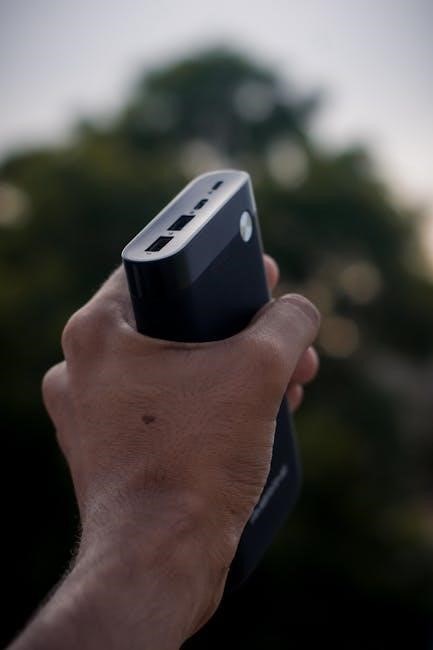
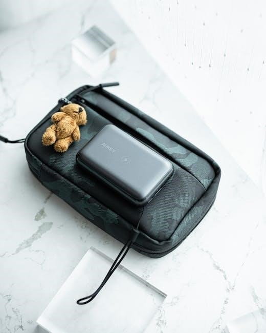
Furthermore‚ the Summit 2 incorporates a storage mode‚ activating after a complete charge cycle to maintain battery health. It utilizes a 2-wire‚ 12AWG cordset with a Lester 2-blade Gray Molded Plug for secure connections. The 1050W V2 model is a popular variant.

Understanding the Charger’s Operation

The Lester Summit 2 intelligently manages charging cycles‚ adapting to battery conditions. Proper profile selection is crucial to avoid faults and ensure optimal performance.

Charging Profiles and Battery Types

Lester Summit 2 chargers utilize specific charging profiles tailored to different battery chemistries. Correct profile selection is paramount for efficient and safe charging‚ preventing damage and maximizing battery lifespan. The charger supports Wet/Flooded‚ AGM‚ and Gel batteries‚ each requiring a unique charging algorithm.

Incorrect profile settings can lead to undercharging‚ overcharging‚ or gassing‚ all detrimental to battery health. The charger’s Bluetooth connectivity allows users to verify and adjust the selected profile. If a fault occurs‚ the charger may indicate a profile mismatch. Refer to the battery manufacturer’s specifications to determine the appropriate charging profile.

Understanding your battery type and corresponding charging requirements is essential. The manual details each profile and its intended use‚ ensuring optimal performance from your Lester charger and battery system.

On-Board vs. Off-Board Charging

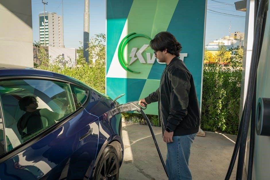
Lester Summit 2 chargers are available in both on-board and off-board configurations‚ each offering distinct advantages. On-board chargers are integrated directly into the vehicle‚ providing convenient charging without the need for external equipment. Off-board chargers are standalone units‚ typically used for greater flexibility and higher charging rates.

On-board operation simplifies the charging process‚ while off-board chargers allow for charging batteries independently of the vehicle. The Summit II series is compatible with both setups. When using an on-board charger‚ ensure proper ventilation to dissipate heat.

The manual details specific operational considerations for each configuration‚ including connection procedures and safety precautions. Proper cordset connection is crucial‚ and care should be taken to avoid movement during charging. Understanding these differences ensures optimal charging performance and longevity.

Troubleshooting Common Issues

Lester Summit 2 chargers can experience issues like failing to power on‚ displaying flashing lights‚ or Bluetooth connectivity problems. This section offers solutions.

Charger Not Lighting Up

If your Lester Summit 2 charger isn’t illuminating‚ several factors could be at play. First‚ meticulously check the power connection – ensure it’s securely plugged into a functioning outlet. Verify the fuse within the charger hasn’t blown; a replacement may be necessary.

Next‚ examine the battery connections. A loose or corroded connection can prevent power flow. Carefully disconnect and reconnect the ring terminals‚ ensuring a firm grip. Be cautious not to move the ring terminals during connection‚ as this can interrupt the process.

The battery itself might be the issue. A severely discharged or damaged battery may not trigger the charger to activate. Finally‚ if none of these steps resolve the problem‚ contacting Lester Electrical Support is recommended for further diagnostics and potential repair options.

Flashing Lights and Error Codes

Lester Summit 2 chargers utilize flashing lights to communicate charging status and potential errors. A slow flash often indicates a battery issue‚ such as being too hot or too cold to charge effectively. Consult the charger’s manual for specific flash patterns and their corresponding meanings.

Error codes‚ accessible via the Bluetooth app‚ provide more detailed diagnostics. A “limit fault” suggests an over/under voltage situation‚ potentially stemming from incorrect battery settings or a failing battery. Incorrect profile settings for the batteries can also cause faults.

If encountering persistent flashing or error codes‚ review the battery profile within the app to ensure it matches your battery type. If the problem persists‚ document the flashing pattern or error code and contact Lester Electrical Support for assistance.

Bluetooth Connectivity Problems

Establishing a Bluetooth connection between your Lester Summit 2 charger and your mobile device is crucial for advanced monitoring and profile adjustments. If you experience connectivity issues‚ ensure Bluetooth is enabled on your device and that the charger is within range.

Attempt to “forget” the charger in your device’s Bluetooth settings and then re-pair it. Ensure no other devices are interfering with the connection. Open the Lester app and attempt to connect; the app is essential for viewing error codes and adjusting settings.

Be cautious when initially connecting the charger to the battery‚ as movement during this process can disrupt the Bluetooth pairing. If problems continue‚ consult the Lester Electrical Support resources or contact their support team for further troubleshooting steps.

Maintenance and Care

Lester recommends storing the Summit 2 charger in a cool‚ dry location. Regularly inspect the cordset for damage and remove batteries when the charger isn’t in use.

Storing the Charger Properly

Proper storage significantly extends the lifespan of your Lester Summit 2 charger. Always store the unit in a cool‚ dry environment‚ shielded from direct sunlight and extreme temperatures. Avoid locations with high humidity or potential water exposure‚ as this can lead to corrosion and internal damage.

Before long-term storage‚ ensure the charger is completely dry and free of any debris. Disconnect the charger from the power source and‚ if applicable‚ disconnect the battery cables. It’s beneficial to coil the cordset neatly to prevent kinks or strain.

Consider covering the charger with a protective dust cover to further safeguard it from environmental contaminants. Regularly checking the storage location for pests or signs of moisture is also advisable. Following these simple steps will ensure your Lester charger remains in optimal condition for years to come.

Cleaning and Inspection

Regular cleaning and inspection are crucial for maintaining the performance and safety of your Lester Summit 2 charger. Before any cleaning‚ always disconnect the charger from both the AC power source and the battery. Use a soft‚ dry cloth to wipe down the exterior casing‚ removing any dust‚ dirt‚ or grime.

Avoid using harsh chemicals‚ solvents‚ or abrasive cleaners‚ as these can damage the charger’s finish and internal components. Inspect the cordset for any signs of wear‚ such as cracks‚ fraying‚ or exposed wires. If damage is detected‚ the cordset should be replaced immediately.

Carefully examine the DC plug and battery terminals for corrosion. Clean any corrosion with a wire brush or a specialized battery terminal cleaner. Ensure all connections are secure and free from obstructions. Consistent cleaning and inspection will help identify potential issues before they escalate‚ ensuring reliable operation.

Technical Specifications

The Lester Summit 2 charger features a 1050W capacity and utilizes a 2 Wire‚ 12AWG cordset with a 9ft length and a Lester 2-blade Gray plug.

Voltage and Amperage Ratings

The Lester Summit II charger is designed to accommodate a range of voltage and amperage requirements‚ crucial for optimal battery charging. While specific ratings vary based on the model within the Summit II series‚ understanding these specifications is vital for safe and effective operation.

Generally‚ these chargers support 36V and 48V battery systems. Amperage output is dynamically adjusted during the charging cycle‚ typically ranging from 20 to 30 amps‚ depending on the battery’s state of charge and selected profile. The charger automatically detects the battery voltage and adjusts accordingly.

It’s essential to verify the input voltage compatibility – typically 120V AC – before connecting the charger to a power source. Always consult the specific model’s documentation for precise voltage and amperage details to ensure compatibility with your battery bank and prevent damage.

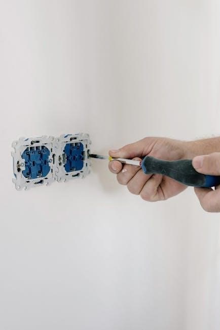
Cordset Information (2 Wire‚ 12AWG)

The Lester Summit II charger utilizes a specific cordset for connecting to the battery. This cordset typically features a 2-wire configuration with 12AWG (American Wire Gauge) conductors‚ ensuring sufficient current carrying capacity for efficient charging. The standard length is 9 feet‚ providing ample reach for most golf cart and industrial battery setups.

The connector end that plugs into the charger itself is a Lester 2-blade design‚ molded with a gray plastic housing. This proprietary connector ensures a secure and reliable connection. It’s crucial to inspect the cordset regularly for any signs of damage‚ such as cuts‚ abrasions‚ or exposed wires.

Replacing a damaged cordset requires using a compatible Lester-approved replacement to maintain safety and performance. Improperly sized or constructed cordsets can pose a fire hazard or damage the charger and battery. Always disconnect the charger from the power source before inspecting or replacing the cordset.

Lester Electrical Support and Resources

Lester provides comprehensive support‚ including downloadable manuals‚ FAQs‚ and direct contact options for assistance with your Summit II charger. Visit www.lester.ru!

Accessing Manuals and FAQs

Lester Electrical makes accessing crucial documentation straightforward. Users can download the Summit II charger’s manual directly from their website‚ www.lester.ru‚ in PDF format. This manual details operation‚ safety precautions‚ and troubleshooting steps.

The website also hosts a frequently asked questions (FAQs) section addressing common issues and providing quick solutions. These FAQs cover topics like flashing lights‚ Bluetooth connectivity‚ and charger operation.

Specifically‚ the Summit Series II 1050W V2 manual is readily available. These resources are designed to empower users to resolve minor problems independently and understand the charger’s functionalities fully. For more complex issues‚ or if the online resources don’t provide a solution‚ contacting Lester’s support team is recommended.

Contacting Lester Electrical Support

For issues not resolved through the manuals or FAQs‚ Lester Electrical provides dedicated support channels. You can reach them via telephone/fax at +7 (495) 961-31-19. Alternatively‚ email inquiries can be sent to infolester.ru.

Their support team is equipped to assist with troubleshooting‚ understanding error codes‚ and providing guidance on charger operation. When contacting support‚ having the charger’s model number and a detailed description of the problem will expedite the process.

Users experiencing Bluetooth connectivity problems or limit faults (over/under voltage) may find direct assistance particularly helpful. Remember to carefully connect the charger to the battery‚ as improper connection can cause issues‚ as advised by Lester’s support staff. Prompt and accurate information ensures efficient resolution.

dynex television manual

Dynex‚ a house brand formerly sold exclusively at Best Buy‚ offered a range of affordable televisions and electronics.
Finding the correct Dynex television manual is crucial for setup‚ operation‚ and troubleshooting.
Numerous resources exist online for downloading these manuals in PDF format‚ aiding users in maximizing their viewing experience.

Dynex produced various models‚ including LCD and LED TVs‚ and even combo units with built-in DVD players.
Accessing the appropriate manual ensures safe usage and unlocks the full potential of your Dynex device.

Overview of the Dynex Brand

Dynex emerged as Best Buy’s in-house brand‚ specializing in providing consumers with budget-friendly electronic options.
Initially focused on accessories‚ Dynex expanded its product line to include televisions‚ aiming to deliver acceptable performance at competitive price points.
The brand catered to customers seeking functional technology without the premium cost associated with established names.

While Dynex televisions weren’t known for cutting-edge features‚ they offered a reliable viewing experience for everyday use.
Manuals for these TVs are essential‚ given the brand’s discontinuation‚ as finding support through traditional channels is now limited.
Dynex’s strategy involved leveraging Best Buy’s retail network for distribution and brand recognition‚ making their products readily accessible.

Despite no longer being actively manufactured‚ a substantial number of Dynex televisions remain in use‚ highlighting the importance of readily available manuals for continued operation and troubleshooting.

Common Dynex TV Models

Dynex produced a variety of television models‚ frequently identified by alphanumeric codes like DX-32L220A12 or DX-32D310NA15.
These models generally ranged in size from smaller 19-inch sets to larger 70-inch flat-panel displays‚ catering to diverse viewing needs.
Many Dynex televisions utilized LCD technology‚ with later models incorporating LED backlighting for improved picture quality.

The DX-15E220A12‚ a 19-inch LCD TV/DVD combo‚ was a popular choice for smaller spaces or secondary rooms.
Other common models included the DX-32L151A11‚ a 32-inch LCD TV‚ and various other 32-inch and 37-inch LCD options.
Locating the specific manual for your Dynex model is vital‚ as features and settings can vary significantly between different series.

Accessing the correct manual ensures you can properly utilize all the features of your particular Dynex television.

Finding Your Dynex Television Manual

Locating your Dynex TV manual is straightforward; official Dynex resources and third-party databases offer PDF downloads for easy access and assistance.

Locating Manuals Online – Official Dynex Resources

Unfortunately‚ as Dynex is a discontinued brand previously exclusive to Best Buy‚ a direct official website hosting manuals no longer exists. However‚ resourceful users can often find archived manuals through Best Buy’s support pages‚ though availability can be limited and inconsistent.

Previously‚ Best Buy provided a dedicated section for Dynex product support‚ including manual downloads. While this direct link is often broken now‚ searching Best Buy’s site using the specific Dynex TV model number (e.g;‚ DX-32L220A12) may yield results. It’s important to note that these resources are not consistently maintained‚ and finding the exact manual can require patience and persistence.

Furthermore‚ exploring Best Buy’s community forums can sometimes uncover links shared by other users who have successfully located and saved Dynex TV manuals. These community-driven resources can be invaluable when official channels fall short.

Third-Party Manual Databases and Websites

Several third-party websites specialize in archiving user manuals for various electronics‚ offering a viable alternative when official resources are unavailable. ManualsBase is a prominent example‚ frequently hosting Dynex television manuals‚ including models like the DX-32D310NA15‚ readily available for download in PDF format.

Additionally‚ ServiceManuals.net provides access to both user and service manuals for Dynex LCD TV products‚ catering to both general users and those seeking repair information. ManualLib and similar platforms also maintain extensive databases‚ increasing the chances of locating the specific manual needed.

However‚ users should exercise caution when downloading from these sites‚ ensuring the PDF is free from malware and originates from a reputable source. Always scan downloaded files with antivirus software before opening them.

Downloading and Saving Manuals in PDF Format

Once you’ve located your Dynex television manual online‚ the process of downloading it is typically straightforward. Most websites offer manuals in PDF format‚ ensuring compatibility across various devices. Simply click the download link‚ and your browser will prompt you to save the file.

It’s recommended to save the PDF to a dedicated folder on your computer‚ such as “TV Manuals‚” for easy access in the future. Consider renaming the file with a descriptive name‚ like “Dynex DX-32L220A12 Manual.pdf‚” to facilitate quick identification.

For added convenience‚ you can also store a copy of the manual on a USB drive or cloud storage service‚ providing access even without an internet connection. Regularly backing up these files ensures you won’t lose access to vital information.

Understanding Your Dynex TV Manual

Your Dynex television’s manual details crucial safety precautions‚ remote control functions‚ setup instructions‚ and connection guides for external devices‚ ensuring optimal use.

Safety Precautions and Warnings

Your Dynex TV manual prominently features vital safety information designed to prevent injury and ensure responsible operation. Manuals consistently emphasize the importance of avoiding water exposure near the device‚ as this presents a significant electrical hazard.

Users are cautioned against attempting self-repair‚ instead recommending professional service for any internal issues. The manual also highlights the need for adequate ventilation to prevent overheating‚ advising against blocking the ventilation openings.

A critical section addresses child safety‚ warning about potential dangers posed by the TV stand tipping over and the small parts potentially causing choking hazards. Always follow the provided instructions for secure mounting and placement. Disconnect the TV during lightning storms to protect it from power surges.

Remote Control Functions and Guide

Dynex television manuals dedicate a substantial section to detailing the functions of the remote control‚ the primary interface for operating your TV. The manual typically begins with a diagram identifying each button and its corresponding action‚ including power‚ volume‚ channel selection‚ and menu navigation.

Specific buttons are explained‚ such as those for input source selection (HDMI‚ AV‚ etc.)‚ picture mode adjustments (Standard‚ Vivid‚ etc.)‚ and accessing smart TV features‚ if applicable. The manual often includes troubleshooting tips for remote control issues‚ like unresponsive buttons or a lack of signal.

Understanding the remote’s functions is key to customizing your viewing experience. Many Dynex remotes also support universal remote functionality‚ allowing control of other devices.

Setting Up Your Dynex Television

Dynex television manuals provide step-by-step instructions for initial setup‚ beginning with unpacking and physically assembling the TV‚ often involving attaching the stand. The manual emphasizes the importance of proper ventilation and placement to prevent overheating.

Connection to an antenna or cable source is detailed‚ alongside guidance on performing an initial channel scan. The manual guides users through the on-screen setup wizard‚ covering language selection‚ time zone configuration‚ and network connectivity for smart TV models.

It stresses the necessity of reading safety precautions before powering on the TV. Proper setup ensures optimal picture and sound quality‚ and a smooth user experience.

Connecting External Devices (HDMI‚ USB‚ etc.)

Dynex television manuals dedicate sections to connecting various external devices‚ primarily focusing on HDMI for high-definition sources like Blu-ray players‚ gaming consoles‚ and cable/satellite boxes. The manual illustrates the location of HDMI ports on the TV and provides clear instructions for selecting the correct input source.

USB ports are explained for connecting flash drives or external hard drives to play media files. Instructions detail compatible file formats. The manual may also cover component and composite video inputs for older devices‚ though HDMI is generally recommended.

Troubleshooting tips for connection issues are often included‚ ensuring a seamless integration of external devices with your Dynex TV.

Troubleshooting Common Dynex TV Issues

Dynex television manuals offer guidance on resolving frequent problems like picture distortion‚ sound loss‚ and connectivity failures.
These sections provide step-by-step solutions for common user issues.

Picture Quality Problems (Blurry‚ Distorted)

Dynex television manuals dedicate sections to addressing picture quality issues‚ such as blurriness or distortion. First‚ verify all cable connections are secure – HDMI or component cables can loosen. The manual advises checking the input source; ensure the correct input is selected on your TV and source device.

Adjusting picture settings is often the solution. Consult your manual for instructions on accessing the picture menu‚ where you can modify brightness‚ contrast‚ sharpness‚ and color levels. Experiment with these settings to find optimal clarity. If the problem persists‚ the manual suggests trying a different resolution on your source device‚ ensuring it’s compatible with your Dynex TV.

Furthermore‚ interference from other electronic devices can sometimes cause distortion. Try moving other electronics away from the TV. The manual may also include a factory reset option as a last resort‚ restoring the TV to its original settings.

Sound Issues (No Sound‚ Low Volume)

Dynex television manuals provide troubleshooting steps for sound problems‚ ranging from complete silence to insufficient volume. Initially‚ confirm the TV isn’t muted and the volume level is appropriately raised using the remote. The manual instructs users to check the audio output settings‚ ensuring the correct source (TV speakers‚ HDMI ARC‚ etc.) is selected.

If using external speakers‚ verify their power and connections. The manual details how to adjust audio settings for different output configurations. Low volume can sometimes be attributed to the audio settings on the connected device – check its volume and output settings as well.

Furthermore‚ the manual suggests testing with a different audio source (another channel‚ a DVD) to isolate the issue. A factory reset‚ as outlined in the manual‚ can resolve software glitches affecting audio output.

Connectivity Problems (HDMI‚ USB)

Dynex television manuals address common connectivity issues with HDMI and USB ports. If a device isn’t recognized‚ the manual advises checking the cable connections at both ends‚ ensuring they are securely plugged in. Try a different HDMI or USB port on the TV‚ as some ports may have limited functionality.

The manual instructs users to verify the connected device is powered on and outputting a signal. For USB devices‚ confirm the TV supports the file format being used. Sometimes‚ cycling the power – unplugging the TV and the connected device for a minute – can resolve communication errors.

Additionally‚ the manual suggests checking for firmware updates for the TV‚ as these often include improved compatibility with various devices. If problems persist‚ consult the manual’s troubleshooting section for specific error codes.

Advanced Dynex TV Features

Dynex television manuals detail menu settings‚ picture adjustments‚ and‚ for Smart TV models‚ network configuration and app usage instructions for enhanced viewing.

Using the TV Menu and Settings

Dynex television manuals provide detailed guidance on navigating the on-screen display (OSD) menu. This menu is your central hub for customizing the viewing experience. Users can adjust picture settings like brightness‚ contrast‚ color‚ and sharpness to optimize image quality based on personal preference and content type.

Sound settings allow control over volume‚ equalization‚ and audio modes. The manual explains how to access and modify these settings for optimal audio performance. Furthermore‚ the menu offers options for channel management‚ input source selection‚ and parental controls. Understanding these settings‚ as outlined in the manual‚ empowers users to tailor their Dynex TV to their specific needs and preferences‚ unlocking its full potential.

Advanced settings may include options for aspect ratio control‚ closed captioning‚ and energy-saving modes.

Understanding Smart TV Functionality (if applicable)

If your Dynex model includes smart TV capabilities‚ the manual details accessing and utilizing built-in apps and online services. These features‚ though limited compared to modern smart TVs‚ typically included access to streaming platforms and internet browsing. The manual explains how to connect to your home Wi-Fi network and navigate the smart hub interface.

Troubleshooting connectivity issues is also covered‚ addressing common problems like failed connections or slow loading times. The Dynex television manual will outline how to update the TV’s firmware‚ ensuring optimal performance and access to the latest features. It’s important to note that older Dynex smart TVs may have limited app support due to outdated software and compatibility issues.

The manual also details any specific remote control functions related to smart TV features.

Dynex TV Service Manuals

Dynex service manuals‚ available online‚ provide detailed diagrams and troubleshooting guides for qualified technicians. These resources aid in TV repair and component-level diagnostics.

Accessing Service Manuals for Repair

Dynex television service manuals are invaluable resources for electronics technicians undertaking repairs. Websites like servicemanuals.net specialize in distributing these often-hard-to-find documents‚ offering both PDF downloads and‚ in some cases‚ physical copies. These manuals contain detailed schematics‚ block diagrams‚ and parts lists essential for diagnosing and resolving complex TV issues.

Accessing these resources requires careful consideration of the specific Dynex model number‚ as manuals are model-specific. Technicians can utilize the manual’s troubleshooting sections to pinpoint faulty components and follow step-by-step repair procedures. Safety precautions are also prominently featured‚ emphasizing the importance of proper handling of electrical components and high-voltage circuits. Remember that working on televisions can be dangerous‚ and professional expertise is recommended.

Understanding Service Manual Diagrams

Dynex television service manuals utilize various diagrams to illustrate internal circuitry and component layouts. Block diagrams provide a high-level overview of the TV’s functional sections‚ such as the power supply‚ video processing‚ and tuner. Schematic diagrams‚ conversely‚ offer a detailed representation of each circuit‚ including component values and connections.

Understanding these diagrams requires familiarity with electronic symbols and circuit analysis techniques. Technicians must be able to trace signal paths‚ identify key components‚ and interpret voltage measurements. Parts lists‚ often accompanying the diagrams‚ detail component specifications and sourcing information. Mastering these visual aids is crucial for efficient troubleshooting and accurate repairs of Dynex televisions‚ ensuring a safe and effective restoration process.

grand teton pellet stove manual

Grand Teton Pellet Stove Manual: A Comprehensive Guide

This manual provides detailed instructions for safe installation, operation, and maintenance of your Grand Teton pellet stove, ensuring efficient and cozy heating.

Welcome to the world of efficient and eco-friendly heating with your new Grand Teton Pellet Stove! This stove represents a significant advancement in home heating technology, offering a cost-effective alternative to traditional wood or oil-based systems. Pellet stoves, like the Grand Teton, utilize compressed wood or biomass pellets, providing consistent heat with minimal environmental impact.

This manual is designed to guide you through every aspect of owning and operating your stove, from initial setup and safe operation to regular maintenance and troubleshooting. Proper understanding of these instructions will maximize performance and longevity.

Safety Precautions and Warnings

Prior to installing and operating your Grand Teton Pellet Stove, carefully review these critical safety guidelines. Improper installation or operation can result in fire, carbon monoxide poisoning, or personal injury. Always ensure adequate ventilation and maintain required clearances from combustible materials.

Never store flammable liquids or materials near the stove. Regularly inspect the venting system for obstructions or damage. Keep children and pets a safe distance from the hot surfaces. Disconnect power before performing any maintenance. Failure to heed these warnings could be hazardous.

Understanding Pellet Stove Components

Your Grand Teton Pellet Stove comprises several key components working in harmony to deliver efficient heat. These include the hopper, which stores the pellet fuel; the burn pot, where combustion occurs; and the exhaust system, safely venting byproducts.

A sophisticated fan regulates airflow, while sensors monitor temperature and operation. Understanding each part’s function is crucial for proper maintenance and troubleshooting. Familiarize yourself with the baffle system, designed to improve combustion efficiency and heat distribution throughout your home.

Hopper and Pellet Fuel Requirements

The Grand Teton Pellet Stove’s hopper capacity dictates how frequently you’ll need to reload fuel. Always use dry, high-quality wood pellets that meet the stove’s specifications – typically 6mm or 8mm diameter. Avoid pellets containing excessive dust or moisture, as these can cause operational issues.

Regularly inspect the hopper for obstructions and ensure the automatic feed system functions smoothly. Do not overfill the hopper, and never introduce foreign objects into the pellet fuel supply. Proper pellet selection is vital for optimal performance.

Burn Pot and Combustion System

The Grand Teton’s burn pot is the heart of the combustion process, where pellets are ignited and burned efficiently. Maintaining a clean burn pot is crucial for optimal heat output and minimal emissions. The combustion system relies on a precise air-to-fuel ratio, controlled by the stove’s internal mechanisms.

Regularly inspect the burn pot for buildup and ensure proper airflow. A properly functioning combustion system ensures complete pellet combustion, maximizing heat and reducing creosote formation within the venting system.

Exhaust System and Venting

Proper venting is paramount for safe and efficient operation of your Grand Teton pellet stove. The exhaust system removes combustion gases, preventing carbon monoxide buildup within your home. Always adhere to local building codes and manufacturer’s specifications regarding venting materials and installation.

Use only approved venting components designed for pellet stoves. Inspect the vent pipe regularly for obstructions or damage. A correctly installed and maintained venting system ensures safe and reliable performance, protecting your family and home.

Installation Procedures

Careful installation is crucial for the safe and effective operation of your Grand Teton pellet stove. Begin by thoroughly reviewing all included instructions and local building codes. Ensure the chosen location meets specified clearance requirements to combustible materials, preventing fire hazards. Proper venting installation, following manufacturer guidelines, is essential for removing exhaust gases safely.

Electrical connection must be grounded correctly to prevent electrical shock. A qualified technician should perform the installation to guarantee compliance and optimal performance.

Clearance Requirements and Placement

Maintaining proper clearances around your Grand Teton pellet stove is paramount for safety. Refer to the detailed diagrams in this manual for specific measurements. Allow adequate space to combustible surfaces – walls, furniture, and flooring – as indicated. The stove should be placed on a non-combustible hearth extending beyond the stove’s dimensions.

Ensure sufficient access for cleaning and maintenance. Avoid placing the stove in high-traffic areas or near flammable liquids. Proper placement contributes to efficient heat distribution and minimizes fire risk.

Venting Installation Guidelines

Proper venting is crucial for safe and efficient operation of your Grand Teton pellet stove. Always use the specified venting components, ensuring they are compatible with the stove model. The vent pipe must maintain a consistent upward slope, preventing condensation buildup. Secure all connections tightly, using approved sealant.

Exterior vent termination requires appropriate clearances from windows, doors, and other structures. Follow local building codes and regulations regarding venting installations. Incorrect venting can lead to carbon monoxide hazards.

Electrical Connection and Grounding

The Grand Teton pellet stove requires a dedicated 120V, 60Hz electrical connection. Ensure the circuit is properly grounded according to local electrical codes. Never connect the stove to an extension cord or multi-outlet adapter. A qualified electrician should perform the electrical connection, verifying correct voltage and grounding.

Improper grounding can create a shock hazard. The stove’s electrical components are sensitive; surges can cause damage. Consider a surge protector for added safety. Disconnect power before performing any maintenance.

Operating Instructions

Before initial startup, verify the burn pot is clean and correctly positioned. Load the hopper with approved pellet fuel, ensuring it’s dry and free of debris. Initiate the startup sequence following the control panel prompts. The stove will automatically ignite the pellets and begin the combustion process.

Monitor the first burn closely, observing flame pattern and smoke output. Adjust heat output and fan speed using the control panel to achieve desired room temperature. Refer to the troubleshooting section if ignition fails or performance is unsatisfactory.

Initial Startup and First Burn

Prior to the first burn, double-check the venting system for proper installation and any obstructions. Ensure the burn pot is correctly seated and free of any packaging materials. Fill the hopper with high-quality, dry pellet fuel. Initiate the startup sequence via the control panel; the stove will begin its automated ignition process.

The initial burn is crucial for curing internal components. Expect a slight odor during this phase, which will dissipate with subsequent use. Monitor the flame and exhaust, ensuring proper combustion. Avoid adjusting settings excessively during the first burn cycle.

Loading Pellet Fuel

Always use dry, high-quality pellet fuel specifically designed for pellet stoves. Carefully lift the hopper lid and slowly pour the pellets into the hopper, avoiding overfilling. Do not introduce foreign objects or debris into the hopper. Regularly check the fuel level, especially during extended cold periods, to prevent interruptions in heat output.

Consistent fuel quality is vital for optimal performance. Avoid using pellets that are dusty, damp, or contain excessive fines. A full hopper provides a substantial fuel reserve, minimizing the frequency of refills and ensuring continuous operation.

Adjusting Heat Output and Fan Speed

Your Grand Teton pellet stove offers adjustable heat output and fan speed settings for customized comfort. Utilize the control panel to select desired heat levels, ranging from low to high. Increasing the fan speed enhances heat distribution but may reduce burn time. Experiment with different combinations to find the optimal balance for your space and preferences.

Monitor room temperature and adjust settings accordingly. Lower settings conserve fuel and provide gentle warmth, while higher settings deliver maximum heat output during colder periods.

Maintenance and Cleaning

Regular maintenance is crucial for optimal performance and longevity of your Grand Teton pellet stove. Daily ash removal prevents buildup and ensures efficient combustion. Weekly cleaning of the burn pot and baffle plate removes residue and maintains proper airflow. An annual professional inspection by a qualified technician is highly recommended.

This inspection should include a thorough examination of the venting system, combustion chamber, and safety controls. Proper maintenance guarantees safe and efficient operation, maximizing your heating investment.

Daily Ash Removal

Consistent daily ash removal is vital for maintaining peak efficiency in your Grand Teton pellet stove. Accumulated ash restricts airflow, hindering combustion and potentially leading to reduced heat output. Use a dedicated ash vacuum, specifically designed for pellet stoves, to safely remove ash from the burn pot and ash pan.

Avoid using a standard household vacuum, as the fine ash can damage the motor and filter. Dispose of ash responsibly in a metal container with a tight-fitting lid, away from combustible materials.

Weekly Burn Pot and Baffle Cleaning

A thorough weekly cleaning of the burn pot and baffle plate is crucial for optimal performance of your Grand Teton pellet stove. Remove any remaining ash and creosote buildup with a brush or scraper. Inspect the baffle for warping or damage, replacing it if necessary.

A clean burn pot ensures proper pellet feed and complete combustion. Regularly cleaning these components prevents restricted airflow and maximizes heat output, contributing to a safer and more efficient heating experience.

Annual Professional Inspection

Schedule an annual inspection with a qualified pellet stove technician to ensure the continued safe and efficient operation of your Grand Teton stove. This comprehensive check includes a thorough examination of the venting system, combustion chamber, and all safety controls.

A professional can identify potential issues like carbon monoxide leaks or hidden creosote buildup, preventing hazards. They will also verify proper functionality and recommend any necessary repairs or adjustments, maximizing your stove’s lifespan and performance.

Troubleshooting Common Issues

Encountering problems with your Grand Teton pellet stove? This section addresses frequent concerns. If the stove fails to ignite, check the pellet level, power supply, and igniter. Poor heat output may indicate insufficient pellet feed or a blocked venting system.

Consult the error code list within this manual for specific diagnostic information. Always disconnect power before attempting any repairs. If issues persist, contact a qualified technician for assistance – do not attempt complex fixes yourself.

Stove Not Igniting

If your Grand Teton pellet stove isn’t igniting, first verify the pellet hopper contains sufficient fuel. Ensure the stove is properly connected to a functioning power source and the igniter is receiving electricity. Check for obstructions within the burn pot, preventing proper pellet flow.

A clogged air intake can also hinder ignition. Always disconnect power before inspecting internal components. If the problem continues, consult the error code section or contact qualified service personnel.

Poor Heat Output

Experiencing insufficient heat from your Grand Teton pellet stove? Begin by confirming adequate pellet fuel levels in the hopper and verifying the fuel quality – damp or low-grade pellets reduce efficiency. Inspect the venting system for blockages, as restricted airflow significantly diminishes heat production.

Also, check the baffle plate for proper positioning and cleanliness. Ensure the fan is operating at the desired speed. If issues persist, a professional inspection is recommended to diagnose potential combustion problems.

Error Codes and Their Meanings

Your Grand Teton pellet stove utilizes error codes to diagnose operational issues. Code E1 typically indicates a problem with the auger motor, preventing pellet delivery. E2 signals a lack of flame, potentially due to a faulty igniter or poor pellet quality. E3 often points to an overheating condition, requiring immediate shutdown.

Consult the complete error code list in the appendix for a comprehensive understanding. Always attempt a system reset before contacting support. Ignoring error codes can lead to further damage.

Parts List and Replacement

Maintaining your Grand Teton pellet stove requires occasional part replacements. Common components include the auger motor, burn pot, blower fan, and various sensors. A detailed parts diagram is included at the rear of this manual, listing part numbers for easy ordering.

Genuine Grand Teton replacement parts are recommended to ensure optimal performance and safety. Contact authorized dealers or our customer support for assistance. Improperly installed parts can void your warranty.

Warranty Information

Your Grand Teton pellet stove is covered by a comprehensive warranty against defects in materials and workmanship. The standard warranty period is five years on major components, including the burn pot and auger, and one year on parts and labor.

This warranty does not cover damage caused by improper installation, misuse, or lack of maintenance. Please retain your proof of purchase for warranty claims. Contact our customer support team to initiate a claim and receive detailed instructions.

Frequently Asked Questions (FAQ)

Q: What type of pellet fuel is recommended? A: We recommend using high-quality, low-moisture wood pellets that meet the PFI standards for optimal performance. Q: How often should I clean the stove? A: Daily ash removal is crucial, with weekly burn pot and baffle cleaning.

Q: What do error codes mean? A: Refer to the troubleshooting section for a detailed explanation of each error code and potential solutions. Regular maintenance extends the life of your Grand Teton stove.

Contact Information and Support

For immediate assistance or technical support regarding your Grand Teton pellet stove, please visit our official website at [insert website address here]. You can also reach our dedicated customer support team via phone at [insert phone number here] during business hours, Monday through Friday, 9 AM to 5 PM EST.

For forum discussions and community support, visit [insert forum address here]. We are committed to providing excellent service and ensuring your complete satisfaction with your heating solution.

th8320u1008 installation manual

Honeywell’s TH8320U1008, part of the VisionPRO 8000 series, offers advanced control․ This 7-day programmable thermostat streamlines home comfort, boosting efficiency with its touchscreen interface․

Overview of the VisionPRO 8000 Series

The Honeywell VisionPRO 8000 series represents a significant leap in home climate control technology․ Designed for ease of use and maximum efficiency, these thermostats, including the TH8320U1008, feature intuitive touchscreen interfaces and comprehensive programming capabilities․ They cater to a wide range of heating and cooling systems, from standard setups to more complex heat pump configurations․

This series prioritizes user experience, offering clear displays and simplified navigation․ The VisionPRO 8000 allows for customized temperature schedules, optimizing comfort while minimizing energy consumption․ Its adaptability extends to incorporating humidity control and external sensors for a truly personalized climate experience․

Installation is streamlined, though careful adherence to provided instructions is crucial for optimal performance and safety․ The series is built with reliability in mind, ensuring long-term, consistent operation; Accessing the user manual, often available as a PDF, is highly recommended for a complete understanding of its features․

Key Features and Benefits

The Honeywell TH8320U1008 boasts a vibrant touchscreen display, simplifying programming and operation․ Its 7-day programmability allows for tailored temperature schedules, maximizing comfort and energy savings․ Compatibility with various systems – including standard and heat pump configurations (1H/1C, 3H/2C) – offers broad applicability․

Key benefits include precise temperature control, reducing energy waste and lowering utility bills․ The humidity control feature enhances indoor air quality and comfort․ Easy access to the user manual (available as a PDF) ensures straightforward installation and troubleshooting․

Furthermore, the thermostat’s responsiveness and reliable operation contribute to long-term satisfaction․ Addressing potential issues, like unresponsive keys, is often resolved by checking ribbon cable connections or battery replacement (2032 wafer and AAA)․ Proper recycling and disposal, guided by local waste management instructions, are also important considerations․

Installation Guide

Proper installation of the TH8320U1008 requires careful adherence to safety precautions and wiring diagrams․ Consult the manual for detailed instructions and system compatibility․

Safety Precautions

Prior to installation, always disconnect power to your heating and cooling system at the breaker box to prevent electrical shock․ Read these instructions carefully before beginning, as failure to follow them could damage the thermostat or create a hazardous situation․

Exercise caution when handling wiring; ensure wires are properly connected and secured to avoid loose connections or short circuits; Never use sharp objects, like pencils or pens, to press the touchscreen keys, as this can cause damage․

If you are uncomfortable with electrical work, consult a qualified HVAC technician for assistance․ Improper wiring can lead to system malfunction or safety hazards․ Be careful to avoid damaging existing wiring during the installation process․ Always verify the system’s voltage requirements before connecting the thermostat․

Proper disposal of old batteries and the thermostat itself is crucial; follow local recycling guidelines․

Tools Required for Installation

For a successful installation of your Honeywell TH8320U1008 thermostat, gather the following tools beforehand․ A small flathead screwdriver will be necessary for terminal block connections and wire securing․ A Phillips head screwdriver is also required for mounting the wallplate and thermostat body․

Wire strippers are essential for preparing the thermostat wires, ensuring clean and secure connections․ A level will help ensure the wallplate is mounted straight for aesthetic appeal and accurate operation․ A voltage tester is highly recommended to verify power is off before working with wiring․

Pencil for marking screw locations on the wall․ Needle-nose pliers can assist with manipulating wires in tight spaces․ Digital Multimeter (optional, but useful for troubleshooting)․ Finally, have a camera or smartphone handy to document existing wiring configurations before disconnecting anything – this is crucial for correct re-installation!

Wallplate Installation

Begin by turning off power to your heating and cooling system at the breaker box․ Carefully remove your old thermostat from the wall, noting the wire connections․ Use the provided template to mark the screw locations for the new Honeywell TH8320U1008 wallplate․

Drill pilot holes if necessary, and securely mount the wallplate to the wall using the provided screws․ Ensure the wallplate is level for a professional appearance․ Gently push the thermostat wires through the opening in the wallplate․

Connect the wires to the appropriate terminals on the wallplate, referencing your system’s wiring diagram and the thermostat’s wiring guide․ Grasp the top and bottom of the wallplate and pull to remove if needed during wiring․ Double-check all connections for tightness and accuracy before proceeding․

Wiring Connections ─ System Types

Proper wiring is crucial for correct operation․ The TH8320U1008 supports various system types․ For Standard Heating and Cooling (1H/1C), connect the wires according to the labeled terminals on the wallplate – typically Rh, Rc, W, Y, and C․

Heat Pump Systems (3H/2C) require more connections, utilizing terminals for auxiliary heat (AUX), reversing valve (O/B), and multiple heating stages․ Refer to your specific heat pump wiring diagram for accurate connections․ The ‘U’ designation indicates universal auto-changeover or manual configuration․

Ensure the ‘C’ wire (common wire) is connected for consistent power․ Incorrect wiring can damage the thermostat or your HVAC system․ Always double-check your connections against the wiring diagram before powering on the system․ If unsure, consult a qualified HVAC technician․

Standard Heating and Cooling (1H/1C)

For conventional systems, the wiring is relatively straightforward․ Connect the Rh (heating power) and Rc (cooling power) wires to their respective terminals․ If you have a single wire for both, use a jumper wire between Rh and Rc․ The W wire controls the heating, connecting it to the W terminal․

The Y wire activates the cooling system, connecting to the Y terminal․ Crucially, a ‘C’ wire (common wire) is needed to provide continuous power to the thermostat․ Connect it to the C terminal․ Without a C wire, the thermostat may not function correctly․

Double-check all connections before proceeding․ Loose or incorrect wiring can lead to system malfunctions․ Refer to your HVAC system’s wiring diagram for confirmation․ Carefully secure each wire to its terminal to ensure a reliable connection․

Heat Pump Systems (3H/2C)

Heat pump wiring is more complex, requiring careful attention to terminal assignments․ Connect Rh and Rc as usual, but utilize the jumper if a single wire serves both․ Three heating wires – W1, W2, and W3 – connect to their designated terminals, controlling different heating stages․

Two cooling wires, Y1 and Y2, connect to the Y terminals, managing cooling stages․ A ‘C’ wire remains essential for continuous power, connecting to the C terminal․ Proper configuration of these wires ensures efficient heating and cooling operation․

Verify your heat pump’s wiring diagram to confirm correct terminal assignments․ Incorrect wiring can damage the system․ Pay close attention to the staging configuration (W1, W2, W3 and Y1, Y2) to optimize performance․ Securely fasten each wire to its terminal for a stable connection․

Thermostat Mounting and Powering On

Once wiring is verified, carefully align the thermostat body with the installed wallplate․ Gently push the thermostat onto the wallplate until it clicks securely into place․ Ensure a flush fit to prevent instability․ Avoid forcing it, as this could damage the connection or the unit itself․

Install fresh batteries – one 2032 wafer battery and two AAA batteries – into the battery compartment․ This provides backup power, maintaining settings during outages․ Confirm correct polarity when inserting the batteries․ The thermostat should power on automatically upon proper mounting and battery installation․

If the screen remains blank, double-check battery installation and wiring connections․ A secure ‘C’ wire connection is crucial for consistent power․ The initial startup may take a few moments as the thermostat calibrates․ Follow the on-screen prompts to set the date, time, and system configuration․

Operating Instructions

The TH8320U1008 features an intuitive touchscreen․ Users can easily navigate menus to program schedules, adjust temperatures, and manage system modes for optimal comfort․

Navigating the Touchscreen Interface

The Honeywell TH8320U1008 boasts a user-friendly touchscreen interface designed for simple operation․ The main screen displays current temperature, setpoint, and system mode․ Tapping the screen activates the menu, revealing options for scheduling, settings, and system information․

Key icons provide quick access to frequently used functions․ The “Hold” button temporarily overrides programmed schedules, while the “Fan” icon controls fan operation․ To adjust the temperature, simply tap the up or down arrows․ Swiping left or right navigates between different screens, such as daily or weekly schedules․

Accessing advanced settings requires navigating through the menu options․ Be careful not to use sharp objects like pens or pencils to press the touchscreen keys, as this could cause damage․ The interface is designed for gentle touch input․ Familiarizing yourself with the icon layout and menu structure will ensure efficient control of your home’s climate․

Programming Temperature Schedules

The TH8320U1008 allows for customized temperature schedules to maximize comfort and energy savings․ Access the scheduling function through the main menu on the touchscreen․ You can program different temperatures for various times of the day and days of the week․

The thermostat supports 7-day programming, enabling unique schedules for weekdays and weekends․ Within each day, you can set multiple “periods” – typically Wake, Leave, Return, and Sleep – each with its own desired temperature․ Adjusting these periods allows you to automatically lower temperatures when you’re away or asleep․

To modify a schedule, select the day and period you wish to change․ Use the touchscreen arrows to adjust the temperature and time․ Remember to save your changes after each adjustment․ The thermostat’s intuitive interface simplifies the process of creating a personalized comfort plan, optimizing energy use and reducing utility bills․

Understanding System Modes (Heat, Cool, Auto, Off)

The Honeywell TH8320U1008 offers four primary system modes: Heat, Cool, Auto, and Off․ Selecting the correct mode ensures your system operates efficiently and maintains desired comfort levels․

In Heat mode, the thermostat activates the heating system when the room temperature falls below the setpoint․ Cool mode activates the cooling system when the temperature rises above the setpoint․ Auto mode intelligently switches between heating and cooling to maintain the set temperature, ideal for fluctuating weather․

The Auto mode requires both heating and cooling systems to be properly configured and connected․ Off mode disables both heating and cooling, providing complete system shutdown․ You can easily switch between these modes via the touchscreen interface․ Understanding these modes allows for precise control over your home’s climate, optimizing both comfort and energy consumption;

Using the Humidity Control Feature

The Honeywell TH8320U1008 offers a humidity control feature, enhancing indoor comfort beyond temperature regulation․ This feature requires a compatible whole-house humidifier or dehumidifier connected to your HVAC system․ Access the humidity settings through the thermostat’s touchscreen interface․

You can set a desired humidity level, typically between 30% and 60%, depending on your preference and climate․ Maintaining optimal humidity levels prevents dryness in winter and excessive moisture in summer․ The thermostat will then activate the humidifier or dehumidifier to reach and maintain the setpoint․

Proper humidity control improves air quality, reduces static electricity, and enhances overall comfort․ The ‘1’ indicator on the thermostat signifies a humidity sensor is present․ Ensure correct wiring during installation for this feature to function correctly, referencing the installation guide for specific wiring configurations․

Troubleshooting

Common issues with the TH8320U1008 include unresponsive keys and power problems․ Check ribbon cable connections and replace batteries (2032 wafer & AAA) for resolution․

Unresponsive Touchscreen Keys

Experiencing unresponsive touchscreen keys on your Honeywell TH8320U1008 thermostat can be frustrating, but often has a simple solution․ The first step in troubleshooting this issue is to carefully inspect the ribbon cable connections located within the thermostat․ Ensure these connections are secure and making firm contact․ A loose or improperly seated ribbon cable is a frequent cause of touchscreen malfunction․

If the ribbon cable appears correctly connected, the next course of action is to address potential power issues․ The TH8320U1008 utilizes both a 2032 wafer battery and AAA batteries to maintain its operation․ Replacing both of these batteries, even if they appear to have some charge remaining, can often restore touchscreen responsiveness․ Low battery power can lead to erratic or non-functional touchscreen behavior․

Be cautious when handling the thermostat’s internal components․ Avoid using sharp objects, such as pencils or pens, to press the touchscreen, as this could cause damage to the display․ If these steps do not resolve the issue, further assistance may be required from a qualified HVAC technician․

Battery Replacement

Maintaining fresh batteries is crucial for the consistent operation of your Honeywell TH8320U1008 thermostat․ This model requires two types of batteries: a 2032 wafer battery and AAA alkaline batteries․ The 2032 wafer battery primarily retains the thermostat’s programming and settings during power outages, while the AAA batteries power the display and touchscreen functionality․

To replace the batteries, locate the battery compartment, typically accessed by removing the thermostat faceplate․ Carefully remove the old batteries, noting the correct polarity (+ and -) for each type․ Insert new, high-quality batteries, ensuring proper alignment․ It’s recommended to replace both battery types simultaneously, even if only one appears depleted․

After battery replacement, verify the thermostat powers on and the touchscreen responds correctly․ If the display remains blank or unresponsive, double-check the battery polarity and ensure the batteries are making good contact․ Proper battery maintenance ensures uninterrupted control of your home’s heating and cooling systems․

Addressing Wiring Issues

Incorrect wiring is a common cause of thermostat malfunctions․ Before addressing any wiring, always disconnect power to your HVAC system at the breaker box to prevent electrical shock․ Carefully inspect all wiring connections at both the thermostat and the furnace/air handler․ Ensure each wire is securely connected to the correct terminal, referencing your system’s wiring diagram․

Loose connections can cause intermittent operation or complete failure․ Gently tug on each wire to verify its secure attachment․ If a wire is loose, tighten the screw terminal or, if necessary, strip a small amount of insulation to expose fresh wire for a better connection․ Never use sharp objects to manipulate the wires․

Misidentified wires can lead to system damage․ If unsure about any wiring, consult a qualified HVAC technician․ Incorrect wiring can cause short circuits or damage to sensitive electronic components․ Double-check the wiring against the thermostat’s manual and your HVAC system’s documentation before restoring power․

Manual Download and Resources

Access the TH8320U1008 user manual PDF online for detailed installation instructions and troubleshooting․ Fire Alarm Resources offers free downloadable manuals․

Accessing the TH8320U1008 User Manual PDF

Finding the official Honeywell TH8320U1008 user manual in PDF format is crucial for a smooth installation and optimal performance․ Several online resources provide direct access to this valuable document․ Fire Alarm Resources is a reliable source, offering a free downloadable PDF containing comprehensive installation instructions, wiring diagrams, and troubleshooting guides․

The PDF manual, spanning 96 pages and approximately 2․96 Mb in size, details every aspect of the thermostat, from initial setup to advanced programming features․ It’s essential to read these instructions carefully before beginning any work, as failure to do so could potentially damage the unit or create a hazardous situation․ The manual also provides important safety precautions to follow throughout the installation process․

You can easily search within the PDF for specific topics, making it convenient to find the information you need quickly․ Downloading and saving the manual to your device ensures you always have access to it, even without an internet connection․ Remember to consult the manual for proper recycling and disposal instructions when the thermostat reaches the end of its lifespan․

Recycling and Disposal Instructions

Responsible disposal of your Honeywell TH8320U1008 thermostat is vital for environmental protection․ This device contains electronic components that require specialized handling and should not be discarded with regular household waste․ Improper disposal can lead to harmful substances leaching into the environment․

To ensure proper recycling, contact your local waste management authority for specific instructions regarding electronic waste (e-waste) disposal in your area․ Many municipalities offer designated e-waste collection events or drop-off locations․ These programs ensure that valuable materials are recovered and reused, minimizing landfill waste․

Before disposal, remove the batteries (2032 wafer and AAA) from the thermostat․ These batteries should be recycled separately at a designated battery recycling facility․ The wallplate can be carefully removed by grasping the top and bottom and gently pulling it away from the wall․ Always follow local regulations and guidelines for electronic waste disposal to contribute to a sustainable future․

hobart handler 210 manual

Hobart Handler 210 Manual: A Comprehensive Guide

This manual provides detailed instructions for the Hobart Handler 210 MVP, covering safety, setup, operation, troubleshooting, maintenance, and technical specifications․

The Hobart Handler 210 MVP is a versatile and popular choice for both beginner and experienced welders, known for its reliability and ease of use․ This machine excels in MIG (GMAW) and Flux-Cored (FCAW) welding applications, making it suitable for a wide range of projects – from automotive repair and home fabrication to light industrial work․

This manual serves as a comprehensive resource, guiding users through every aspect of the Handler 210 MVP․ It details essential safety precautions, provides step-by-step setup instructions, and explains the intricacies of operating the machine effectively․ Furthermore, it offers valuable troubleshooting advice for common issues, alongside routine maintenance procedures to ensure longevity․ Understanding the capabilities and limitations of your welding equipment is paramount for achieving quality results and maintaining a safe working environment․ This guide aims to empower you with the knowledge needed to maximize the potential of your Hobart Handler 210 MVP․

Understanding the Handler 210 MVP’s Capabilities

The Hobart Handler 210 MVP is designed for welding steel and aluminum, accommodating wire diameters suitable for various thicknesses․ Its amperage range allows for working with different materials and achieving desired weld penetration․ The machine’s processes include both MIG (GMAW) and Flux-Cored (FCAW) welding, offering flexibility for diverse applications․

Crucially, the Handler 210 MVP features built-in circuit protection, ensuring operational safety and component longevity, adhering to NEC standards․ Understanding the duty cycle is vital; it dictates the maximum welding time within a specific period before requiring a cool-down․ The machine’s voltage and amperage ranges determine its suitability for different projects․ Recognizing these capabilities allows users to optimize settings for specific materials and welding techniques, resulting in stronger, cleaner, and more reliable welds․ Proper utilization of these features maximizes the machine’s performance and extends its lifespan․

Safety Precautions & Setup

Prioritize safety by reviewing essential guidelines before operation, ensuring proper grounding and ventilation․ Correct setup and component identification are crucial for safe welding․

Essential Safety Guidelines for Operation

Welding with the Hobart Handler 210 MVP demands strict adherence to safety protocols․ Always wear appropriate personal protective equipment (PPE), including a welding helmet with the correct shade, gloves, and fire-resistant clothing․ Ensure adequate ventilation to avoid inhaling fumes; work in a well-ventilated area or use a fume extractor․

Inspect the work area for flammable materials, removing them before commencing welding․ Never weld on containers that have held flammable substances․ Be mindful of electrical hazards – ensure proper grounding and avoid welding in damp environments․ Disconnect power before performing maintenance or replacing parts․

Avoid touching electrically live parts․ Understand the risks associated with arc welding, including burns and eye damage․ Keep bystanders at a safe distance, utilizing a welding screen if necessary․ Follow all applicable safety regulations and guidelines for welding operations, prioritizing a secure working environment․

Initial Setup and Component Identification

Upon unboxing your Hobart Handler 210 MVP, carefully identify all components․ These include the power source, wire feeder, welding gun, ground clamp, electrode holder, and gas nozzle․ Familiarize yourself with the location of the polarity switch, voltage control, and wire feed speed adjustment․

Inspect all cables and connections for damage․ Ensure the drive rolls are correctly installed for the wire type you intend to use․ Attach the welding gun and ground clamp securely․ Verify the gas nozzle is properly fitted if using shielding gas․

Refer to the included diagrams in the manual for a detailed component layout․ Understanding each part’s function is crucial for proper setup and operation․ Double-check all connections before proceeding to the power connection stage, ensuring everything is secure and ready for use;

Connecting the Handler 210 to Power

Before connecting the Hobart Handler 210 to a power source, ensure the unit is switched off․ Verify your power supply matches the welder’s voltage requirements – typically 120V or 240V, depending on the model and configuration․ Use the appropriate power cord and plug, ensuring it’s in good condition․

Connect the power cord to a dedicated circuit, avoiding shared outlets with other high-demand appliances․ This prevents potential voltage drops and circuit breaker tripping․ Confirm the circuit protection device is compatible with the welder’s amperage draw, as outlined in the technical specifications․

Always adhere to NEC articles 210․21 and 630․11 for safe electrical installation․ Once connected, double-check all connections before switching the welder on․

Operating Instructions

Proper operation involves selecting the correct wire, setting voltage and wire feed speed, understanding polarity, and skillfully initiating and maintaining a stable welding arc․

Selecting the Correct Welding Wire

Choosing the appropriate welding wire is crucial for optimal performance with your Hobart Handler 210 MVP․ The wire diameter must be compatible with the machine’s specifications – refer to the technical specifications section for supported sizes․ Consider the material you’re welding; mild steel typically uses ER70S-6 wire, while stainless steel requires different compositions like ER308L or ER309L․

Flux-cored wires are also an option, offering benefits for thicker materials or outdoor use․ Ensure the wire is clean, dry, and free of rust or contaminants, as these can cause porosity and weak welds․ Proper wire selection directly impacts weld quality, arc stability, and overall efficiency․ Always consult the material manufacturer’s recommendations for the best wire type for your specific application․ Incorrect wire selection can lead to poor weld penetration, excessive spatter, and potential structural failures․

Setting Voltage and Wire Feed Speed

Achieving a quality weld with the Hobart Handler 210 MVP requires precise voltage and wire feed speed settings․ These settings are interdependent; increasing one often necessitates adjusting the other․ Start with the recommended settings chart provided in the manual for the specific wire diameter and material thickness you’re using․

Voltage controls the arc length and penetration, while wire feed speed dictates the amount of filler metal deposited․ Lower voltage and slower feed speeds are suitable for thinner materials, while higher settings are needed for thicker sections․ Listen to the arc sound – a smooth, consistent buzzing indicates proper settings․ Adjust voltage incrementally to fine-tune arc characteristics and minimize spatter․ Experimentation and practice are key to mastering these adjustments for various welding scenarios․

Understanding the Polarity Switch

The polarity switch on the Hobart Handler 210 MVP is crucial for selecting the correct electrical current direction for different welding processes and wire types․ MIG (GMAW) welding typically uses DCEN (Direct Current Electrode Negative), where the electrode (wire) is negative and the workpiece is positive․ This concentrates heat on the workpiece, promoting deeper penetration․

Flux-cored welding, however, often requires DCEP (Direct Current Electrode Positive), reversing the polarity․ This provides better arc stability and reduces spatter when using self-shielded flux-cored wire․ Incorrect polarity can lead to unstable arcs, poor weld quality, and excessive spatter․ Always verify the recommended polarity for your chosen wire type in the Hobart manual or wire manufacturer’s specifications before initiating a weld․

Initiating and Maintaining an Arc

To initiate an arc with the Hobart Handler 210 MVP, ensure proper setup – correct polarity, wire tension, and voltage/wire feed speed settings are essential․ Approach the workpiece at a slight angle, maintaining a consistent work distance (typically 3/8 to 3/4 inch)․ Briefly touch the wire to the workpiece and immediately lift it slightly, creating a short circuit․ This initiates the arc․

Maintaining a stable arc requires consistent travel speed and work angle․ Listen to the sound of the arc – a smooth, sizzling sound indicates a good weld․ Erratic or sputtering sounds suggest adjustments are needed․ Avoid excessive weaving or erratic movements․ Practice consistent technique to achieve uniform weld beads․ Remember safety precautions, including wearing appropriate PPE, throughout the welding process․

Troubleshooting Common Issues

This section details solutions for frequent problems like no weld output, wire feed issues, a non-running fan, and power switch failures, aiding quick repairs․

No Weld Output: A Diagnostic Approach

When encountering no weld output with your Hobart Handler 210 MVP, a systematic approach is crucial․ First, verify power supply and connections – ensure the machine is properly plugged in and the circuit breaker hasn’t tripped․ Next, inspect the wire feed; if the wire isn’t advancing, check the drive rolls for proper tension and condition․

A common issue, as reported on Reddit’s r/Welding, involves the power switch itself, with a plastic spring prone to breakage, necessitating replacement․ Also, examine the large white plug connecting to the board, ensuring it’s securely locked in, as harness winding tightness can cause connection problems, according to Miller Welding Discussion Forums․ If the fan is running but there’s still no weld, it suggests a different issue than if the fan isn’t operating․ Consult the troubleshooting table in the owner’s manual (ManualsLib) for specific guidance based on these observations․

Wire Feed Problems and Solutions

Addressing wire feed issues on the Hobart Handler 210 MVP begins with verifying proper drive roll tension․ Insufficient tension results in slipping, while excessive tension can deform the wire․ Regularly inspect the drive rolls themselves for wear or damage, replacing them as needed․ Ensure the correct drive roll type is installed for the wire diameter being used․

A frequently encountered problem, highlighted in online forums, involves the harness connections․ A tightly wound harness can prevent the large white plug from fully seating within the control board, interrupting the wire feed․ Confirm this plug is securely locked in place․ If the wire still fails to feed despite these checks, examine the wire spool for binding or tangling․ Finally, consult the Hobart Handler 210 MVP owner’s manual’s troubleshooting section (ManualsLib) for a comprehensive diagnostic table, covering scenarios where the fan operates or doesn’t during a feed failure․

Fan Not Running: Causes and Fixes

A non-operational fan on the Hobart Handler 210 MVP often accompanies a “no weld output” scenario, as detailed in troubleshooting guides (ManualsLib)․ However, the fan can fail independently․ Begin by verifying power is reaching the unit and the power switch is fully engaged – a common issue involves a broken plastic spring within the switch itself, necessitating replacement (Reddit r/Welding)․

If power is confirmed, inspect the fan motor for obstructions or physical damage․ A seized motor requires replacement․ Check the wiring harness connecting to the fan for loose connections or breaks․ A faulty harness, as noted in Miller Welding Discussion Forums, can disrupt power delivery․ If the fan doesn’t run while welding, but operates during initial power-up, the thermal overload protection might be activating; reduce welding amperage or allow the unit to cool․

Power Switch Failure & Replacement

The Hobart Handler 210 MVP’s power switch is a frequent point of failure, often due to a broken internal plastic spring (Reddit r/Welding); This breakage prevents consistent contact, leading to intermittent or complete power loss․ Rather than attempting repair, replacement is recommended, and sourcing multiple switches as spares is a cost-effective strategy, given the recurring nature of this issue․

Replacement is relatively straightforward․ Disconnect the machine from power! Remove the control panel cover to access the switch․ Carefully disconnect the wiring harness from the old switch, noting the connection points for accurate reassembly․ Install the new switch, ensuring secure harness connections․ Reattach the control panel cover․ Testing involves verifying consistent power-on functionality․ If issues persist, double-check wiring and consider potential harness problems, as tight winding can affect connector seating (Miller Welding Discussion Forums)․

Maintenance and Repair

Regular upkeep ensures optimal performance and longevity of your Hobart Handler 210 MVP, including cleaning, drive roll inspection, and addressing potential harness connection issues․

Routine Maintenance Procedures

To maintain peak performance of your Hobart Handler 210 MVP, consistent routine maintenance is crucial․ Regularly inspect the welding cables for any signs of damage, such as cracks or fraying, and replace them if necessary․ Clean the welding contact tip frequently to ensure a smooth and consistent weld․ Dust and debris accumulation can hinder performance, so keep the machine’s exterior clean with a dry cloth․

Periodically check the gas nozzle for obstructions and clean it to maintain proper gas flow․ Inspect the drive rolls for wear and tear, replacing them as needed to prevent slippage and ensure consistent wire feeding․ Furthermore, examine all electrical connections for tightness and corrosion, addressing any issues promptly․ Following these simple procedures will significantly extend the life of your welding machine and ensure reliable operation for years to come․

Cleaning the Handler 210

Maintaining a clean Hobart Handler 210 MVP is essential for optimal performance and longevity․ Before any cleaning procedure, always disconnect the power cord to prevent electrical shock․ Use a dry cloth to wipe down the exterior surfaces, removing dust, dirt, and welding spatter․ Avoid using solvents or abrasive cleaners, as these can damage the machine’s finish․

Pay particular attention to the wire feed mechanism, ensuring it’s free from debris that could impede wire feeding․ Regularly clean the contact tip and gas nozzle to maintain consistent weld quality․ Compressed air can be used cautiously to remove dust from internal components, but avoid directing air into sensitive areas․ A clean machine operates more efficiently and reduces the risk of malfunctions, ensuring a reliable welding experience․

Inspecting and Replacing Drive Rolls

Regularly inspecting the drive rolls on your Hobart Handler 210 MVP is crucial for consistent wire feeding․ Over time, these rolls can become worn or damaged, leading to slippage and poor weld quality․ Disconnect the power before inspection․ Examine the drive rolls for grooves, cracks, or buildup of welding residue․ If any damage is detected, replacement is necessary․

To replace the drive rolls, loosen the tension adjustment knob and remove the old rolls․ Ensure the new drive rolls are correctly matched to the wire diameter being used․ Install the new rolls, aligning them properly with the wire feed path, and re-tighten the tension adjustment knob․ Proper drive roll maintenance ensures smooth and reliable wire feeding, contributing to cleaner, stronger welds and extending the life of your welding machine․

Addressing Harness Connection Issues

Harness connection problems can manifest as intermittent welding, no weld output, or erratic wire feeding on the Hobart Handler 210 MVP․ A common issue involves the large white plug connecting to the control board, sometimes wound too tightly during manufacturing, preventing a secure lock․ Disconnect power before inspecting․

Carefully examine all harness connections for looseness, corrosion, or damaged wires․ Ensure each plug is fully seated and locked into place․ Gently wiggle the harness to check for intermittent connections․ If a harness is damaged, it requires replacement․ Bill at Hobart tech support confirmed this is a frequent cause․ Securely reconnecting or replacing faulty harnesses restores reliable operation and prevents further issues, ensuring consistent welding performance and minimizing downtime․

Technical Specifications

The Hobart Handler 210 MVP offers versatile voltage and amperage ranges, accommodating various wire diameters and duty cycles, alongside robust circuit protection features․

Voltage and Amperage Ranges

The Hobart Handler 210 MVP is designed with a broad input voltage range, typically operating on standard 120V or 240V power supplies, offering flexibility for various workshop setups․ Its output amperage spans from a low of 80 amps, suitable for thin gauge materials, up to a maximum of 210 amps, capable of handling thicker steel․

Voltage control is finely adjustable, allowing welders to precisely tailor the arc characteristics to the specific application and material thickness․ This control is crucial for achieving optimal weld penetration and bead appearance․ The machine’s ability to deliver consistent power across this range ensures stable arc performance, minimizing spatter and improving weld quality․ Understanding these ranges is fundamental for successful welding with the Handler 210 MVP, enabling users to maximize its capabilities for diverse projects․

Wire Diameter Compatibility

The Hobart Handler 210 MVP demonstrates versatility through its compatibility with a range of wire diameters, accommodating diverse welding needs․ It efficiently handles ․024 inch (0․6 mm) wire, ideal for lighter gauge metals and intricate work, extending up to ․035 inch (0․9 mm) for more substantial projects․ Furthermore, it supports ․045 inch (1․2 mm) wire, enabling welding on thicker materials with increased deposition rates․

This compatibility extends to both solid wires for MIG welding and flux-cored wires for self-shielded or gas-shielded FCAW applications․ Proper wire diameter selection is crucial for achieving optimal weld quality, arc stability, and penetration․ Utilizing the correct wire size, in conjunction with appropriate voltage and wire feed speed settings, ensures efficient and reliable welding performance with the Handler 210 MVP․

Duty Cycle Information

Understanding the duty cycle of the Hobart Handler 210 MVP is crucial for preventing overheating and ensuring long-term reliability․ The duty cycle represents the percentage of time within a 10-minute period that the welder can operate at a specific amperage without exceeding its thermal limits․ At 90 amps, the Handler 210 MVP boasts a 60% duty cycle, meaning it can weld continuously for 6 minutes out of every 10 at that setting․

As amperage increases, the duty cycle decreases․ Exceeding the duty cycle can trigger the thermal overload protection, shutting down the machine until it cools․ Monitoring weld times and allowing adequate cooling periods between welds are essential for maintaining optimal performance and preventing premature wear․ Proper ventilation also contributes to efficient heat dissipation, maximizing the welder’s operational lifespan․

Circuit Protection Details

The Hobart Handler 210 MVP incorporates robust circuit protection to safeguard both the welder and the operator․ It features overcurrent protection, preventing damage from excessive amperage draw, and thermal overload protection, which shuts down the machine if it overheats during operation․ These systems are vital for maintaining the welder’s integrity and preventing potential hazards․

The manual emphasizes the importance of physically compatible components within the welding circuit, referencing NEC articles 210․21 and 630․11․ Proper grounding is also critical for electrical safety․ The circuit protection device’s functionality relies on all components being correctly installed and functioning․ Regularly inspect wiring and connections to ensure optimal protection and prevent unexpected interruptions during welding tasks․ Adhering to these guidelines ensures a safe and reliable welding experience․

2019 honda crv manual

The 2019 Honda CR-V owner’s manual‚ available as a 169-page document‚ provides essential guidance for vehicle operation and maintenance.

Understanding this manual is crucial for maximizing your driving experience and ensuring the longevity of your 2019 CR-V.

Overview of the 2019 CR-V

The 2019 Honda CR-V represents a popular choice in the compact SUV segment‚ known for its reliability and versatility. This model year continues Honda’s tradition of offering a well-rounded vehicle suitable for families and individuals alike.

Key features include a spacious interior‚ efficient engine options‚ and available all-wheel drive. The 2019 CR-V also boasts advanced safety technologies‚ particularly within the Honda Sensing suite. Owners will find detailed information regarding these features‚ along with operating procedures‚ within the comprehensive owner’s manual.

The manual serves as a vital resource for understanding the vehicle’s capabilities and ensuring proper maintenance‚ contributing to a safe and enjoyable ownership experience. It covers everything from basic controls to more complex systems.

Importance of the Owner’s Manual

The 2019 Honda CR-V owner’s manual is far more than just a collection of pages; it’s a critical guide to understanding your vehicle’s intricacies. It details safety information and essential operating procedures‚ ensuring both driver and passenger well-being.

Properly utilizing the manual allows owners to maximize the vehicle’s features‚ from the infotainment system to Honda Sensing. It also outlines the recommended maintenance schedule‚ protecting your investment and preventing potential issues.

Furthermore‚ the manual provides insight into diagnostic information uploads and warranty coverage details‚ empowering owners with knowledge and peace of mind. Ignoring the manual can lead to improper use and potentially void warranty claims.

Accessing the 2019 Honda CR-V Manual

The 2019 Honda CR-V manual is readily accessible via PDF download‚ the Honda Owners website‚ and‚ in Canada‚ a CD-ROM format.

Downloading the PDF Version

Accessing the 2019 Honda CR-V owner’s manual in PDF format is a convenient way to have vital vehicle information at your fingertips. Numerous online resources offer direct downloads of this 169-page document. This digital version mirrors the printed manual‚ containing all the essential details regarding operation‚ maintenance‚ and safety features.

Downloading the PDF allows for easy searching of specific topics‚ making it simple to find answers to your questions quickly. You can store it on your computer‚ tablet‚ or smartphone for access anytime‚ anywhere. This eliminates the need to carry a physical copy and ensures you always have the information you need while on the road or performing vehicle upkeep. The PDF version is a valuable tool for all 2019 CR-V owners.

Honda Owners Website

Honda’s official owners website‚ owners.honda.com‚ serves as a central hub for all your vehicle-related needs‚ including access to the 2019 CR-V owner’s manual. Beyond the downloadable PDF‚ the website offers a wealth of resources designed to enhance your ownership experience. You’ll find navigation manuals‚ helpful playlists demonstrating vehicle features‚ and personalized vehicle information.

The site allows you to personalize your vehicle profile‚ potentially unlocking tailored content and support. Honda also provides access to Honda Tech Tutor‚ offering further guidance and tutorials. Regularly visiting owners.honda.com ensures you stay informed about important updates‚ recalls‚ and maintenance recommendations specific to your 2019 CR-V‚ maximizing its performance and longevity.

CD-ROM Availability (Canada)

For 2019 Honda CR-V owners in Canada‚ a physical copy of the owner’s manual was also available on CD-ROM‚ published by Honda Canada. This CD-ROM‚ approximately 52.3MB in size‚ contains the complete owner’s manual‚ including vital warranty information and details on how to contact Honda customer support.

This format provided an offline resource for those preferring not to rely solely on digital downloads or online access. The CD-ROM encompassed all the essential information found in the downloadable PDF version‚ ensuring Canadian owners had comprehensive guidance for operating and maintaining their vehicles. It was released in 2019 and included all relevant details for the 2019 CR-V model.

Key Sections of the Manual

The 2019 Honda CR-V manual details crucial sections covering safety warnings‚ detailed operating procedures‚ and a comprehensive vehicle maintenance schedule for optimal performance.

Safety Information and Warnings

The 2019 Honda CR-V owner’s manual prioritizes safety‚ dedicating a significant portion to vital information and warnings. This section comprehensively outlines procedures to help owners make informed decisions regarding vehicle safety.

It covers critical aspects like proper seatbelt usage‚ airbag system details‚ and child safety seat installation guidelines. Furthermore‚ the manual details essential warnings concerning vehicle operation‚ potential hazards‚ and preventative measures to minimize risks.

Owners will find detailed instructions on handling emergency situations‚ understanding warning lights‚ and recognizing potential mechanical issues that could compromise safety. Adhering to these guidelines is paramount for a secure driving experience.

Operating Procedures

The 2019 Honda CR-V manual provides detailed operating procedures for all vehicle functions. This section guides owners through the correct usage of features‚ ensuring optimal performance and preventing potential damage.

It covers essential aspects like starting and stopping the engine‚ utilizing the transmission‚ understanding the instrument panel‚ and operating the climate control system. Detailed instructions are provided for features like the infotainment system‚ power windows‚ and door locks.

The manual also explains how to properly use various controls and systems‚ maximizing convenience and enhancing the overall driving experience. Following these procedures ensures safe and efficient vehicle operation.

Maintenance Schedule

The 2019 Honda CR-V owner’s manual outlines a comprehensive maintenance schedule crucial for preserving vehicle reliability and performance. This schedule details recommended service intervals for various components‚ including oil changes‚ filter replacements‚ and fluid checks.

Adhering to this schedule helps prevent unexpected breakdowns and costly repairs‚ ensuring the longevity of your CR-V. The manual specifies maintenance tasks based on mileage and time‚ providing clear guidance for owners.

Regular maintenance‚ as outlined‚ is vital for maintaining warranty coverage and optimizing fuel efficiency. Following the recommended schedule contributes to a safer and more enjoyable driving experience.

Vehicle Specific Features Explained

The 2019 Honda CR-V manual details features like Honda Sensing‚ the infotainment system‚ and diagnostic information uploads for optimal vehicle understanding.

Honda Sensing Suite

The 2019 Honda CR-V manual dedicates significant attention to the Honda Sensing suite‚ a collection of advanced safety and driver-assistive technologies. This section thoroughly explains each feature‚ including Collision Mitigation Braking System (CMBS)‚ Road Departure Mitigation System (RDMS)‚ Adaptive Cruise Control (ACC)‚ and Lane Keeping Assist System (LKAS).

Owners will find detailed descriptions of how each system functions‚ its limitations‚ and important warnings regarding its use. The manual emphasizes that Honda Sensing is designed to assist the driver‚ not replace them‚ and responsible driving practices are always essential. Understanding these systems‚ as outlined in the manual‚ is key to maximizing their benefits and ensuring safe operation of the vehicle.

Infotainment System Guide

The 2019 Honda CR-V manual provides a comprehensive guide to the vehicle’s infotainment system. It details operation of the touchscreen display‚ audio controls‚ Bluetooth connectivity‚ and smartphone integration features like Apple CarPlay and Android Auto.

The manual explains navigation system usage‚ voice recognition commands‚ and customization options for the display. It also covers troubleshooting common issues‚ such as pairing devices or updating software. Owners can learn how to access various apps and features‚ ensuring they fully utilize the system’s capabilities. The guide emphasizes accessing further support at owners.honda.com and hondatechtutor.com for personalized assistance.

Understanding Diagnostic Information Uploads

The 2019 Honda CR-V manual explains that certain diagnostic and maintenance data is automatically uploaded to Honda upon vehicle startup. This data transmission helps Honda monitor vehicle performance and identify potential issues proactively.

The manual clarifies the type of information collected and its purpose‚ assuring owners about data privacy. It details how this data assists Honda in improving vehicle reliability and offering better service. Specific references‚ like “19 CR-V ELP HCM MAP HMIN-31TLA6200.book”‚ indicate detailed technical documentation within the manual. Understanding this feature allows owners to be informed about Honda’s ongoing efforts to enhance vehicle quality and support.

Troubleshooting Common Issues

The 2019 Honda CR-V manual offers guidance on jump starting‚ the TPMS system‚ and basic maintenance‚ helping owners resolve frequent vehicle problems independently.

Jump Starting Procedures

The 2019 Honda CR-V owner’s manual details safe jump starting procedures‚ crucial when encountering a discharged battery. It emphasizes using properly rated jumper cables and connecting them in the correct sequence – positive to positive‚ then negative to a grounded metal part of the disabled vehicle.

The manual cautions against connecting the negative cable directly to the battery terminal of the dead battery‚ to minimize spark risk. Following these steps‚ as outlined in the manual‚ ensures a safe and effective jump start‚ preventing potential damage to the vehicle’s electrical system. Always consult the manual for specific instructions and safety precautions before attempting a jump start.

Tire Pressure Monitoring System (TPMS)

The 2019 Honda CR-V’s Tire Pressure Monitoring System (TPMS) is a vital safety feature‚ covered extensively in the owner’s manual. This system alerts the driver when tire pressure is significantly low‚ potentially preventing accidents caused by underinflation;

The manual explains how the TPMS indicator illuminates on the dashboard when pressure drops below recommended levels. It details the importance of checking tire pressure regularly‚ even if the warning light isn’t active‚ and provides recommended pressure values; Proper tire inflation‚ as described in the manual‚ improves fuel efficiency and extends tire lifespan. Refer to the manual for reset procedures after inflation.

Basic Maintenance Tasks

The 2019 Honda CR-V owner’s manual outlines essential basic maintenance tasks to keep your vehicle running smoothly. These include regular oil changes‚ fluid level checks (coolant‚ brake fluid‚ power steering fluid‚ and windshield washer fluid)‚ and air filter replacements.

The manual provides a detailed maintenance schedule‚ specifying intervals for each task. It also offers guidance on inspecting and replacing wiper blades‚ checking lights‚ and ensuring proper battery terminal connections. Performing these tasks‚ as described‚ helps prevent costly repairs and maintains optimal vehicle performance. Always consult the manual before attempting any maintenance.

Warranty Information

The 2019 Honda CR-V manual details warranty coverage and provides contact information for Honda Customer Support regarding any warranty claims.

Warranty Coverage Details

The 2019 Honda CR-V’s warranty‚ as outlined in the owner’s manual‚ offers comprehensive coverage for various vehicle components. This includes a basic warranty protecting against defects in materials and workmanship for a specified period. Additionally‚ a powertrain warranty safeguards the engine‚ transmission‚ and drivetrain.

Specific details regarding the duration and mileage limitations for each warranty component are clearly stated within the manual. Owners should carefully review these details to understand their rights and responsibilities. The manual also outlines what is not covered under warranty‚ such as normal wear and tear or damage resulting from improper maintenance.

Furthermore‚ the 2019 CR-V manual provides information on how to file a warranty claim and the necessary documentation required.

Contacting Honda Customer Support

Honda provides multiple avenues for owners of the 2019 CR-V to access customer support. The owner’s manual directs users to the official Honda website‚ owners.honda.com‚ as a primary resource for information and assistance. This online portal offers FAQs‚ troubleshooting guides‚ and access to digital versions of the owner’s manual itself.

For direct assistance‚ Honda customer service can be reached through their dedicated phone lines. The manual details these contact numbers‚ ensuring owners can quickly connect with a representative. Additionally‚ Honda encourages owners to visit authorized dealerships for personalized support and service.

The 2019 CR-V manual also contains warranty and contact information on the CD-ROM (Canada) and provides links to Honda Tech Tutor for further guidance.

pastors manual

Pastoral care, a vital practice, demands resources; this manual provides essential guidance for navigating ministry, offering support, and fostering spiritual growth within a congregation․

1․1 The Role of the Pastor

The pastor’s role extends far beyond sermon preparation and Sunday service leadership; it’s fundamentally the “practice of grace,” as Lee Eclov aptly states․ This encompasses a holistic approach to shepherding a flock, requiring a deep commitment to understanding and addressing the diverse needs within the congregation․

Pastors are called to cultivate quality relationships, enabling individuals to recognize, follow, and emulate Jesus Christ․ This involves active listening, empathetic communication, and providing support during both joyous occasions and times of crisis․ They are not merely religious leaders, but compassionate caregivers offering holistic support for personal challenges․

Effective pastoral work necessitates a blend of spiritual insight, interpersonal skills, and a willingness to continually learn and adapt․ The pastor serves as a guide, a counselor, and a source of encouragement, always striving to reflect the love and compassion of Christ in every interaction․ Ultimately, the pastor’s role is to equip and empower believers to live fulfilling lives rooted in faith․

1․2 Defining Pastoral Care

Pastoral care is a multifaceted ministry extending beyond solely spiritual concerns, encompassing comprehensive support for life’s challenges․ It’s about meeting people where they are, acknowledging their pain, and offering a listening ear coupled with compassionate guidance․ This practice isn’t limited to formal counseling sessions, but permeates every interaction within the church community․

At its core, pastoral care involves developing genuine relationships, fostering an environment of trust and vulnerability․ It requires recognizing individual needs – emotional, relational, and even practical – and responding with grace and empathy․ Resources are vital for pastors to effectively navigate these complex situations․

This form of care aims to help individuals navigate spiritual struggles, emotional crises, and life transitions, ultimately guiding them towards wholeness and a deeper connection with God․ It’s a continuous process of listening, praying, offering comfort, and pointing people towards the transformative power of faith, mirroring Christ’s loving approach․

1․3 The Importance of a Pastor’s Manual

A pastor’s manual is an indispensable tool, serving as a central repository of knowledge and practical guidance for navigating the complexities of ministry․ It equips pastors to effectively practice grace – their “stock-in-trade” – and provide consistent, biblically-sound care to their congregations․ Without such a resource, ministers may find themselves unprepared for the diverse needs they encounter․

This manual consolidates essential resources, from recommended books and online tools to strategies for crisis intervention and grief counseling․ It aids in building a strong pastoral care team, ensuring comprehensive support for the church family․ It’s a proactive measure against burnout, offering guidance on self-care and seeking mentorship․

Furthermore, a well-crafted manual helps pastors address contemporary issues with sensitivity and wisdom, including mental health awareness and navigating sensitive topics like same-sex attraction․ It’s a commitment to ongoing learning and professional development, ultimately enhancing the pastor’s ability to serve effectively․

II․ Foundational Principles of Pastoral Care

Pastoral care rests on biblical foundations, understanding human needs holistically, and consistently practicing grace in all interactions, fostering quality relationships mirroring Jesus’ example․

2․1 Biblical Basis for Pastoral Care

The scriptural foundation for pastoral care is deeply rooted in the example of Jesus Christ, the Good Shepherd who tirelessly sought out and ministered to the lost, the hurting, and the marginalized․ Throughout the Gospels, we witness His compassionate engagement with individuals facing diverse struggles – physical ailments, emotional distress, spiritual emptiness, and societal ostracism․

This model of empathetic care is echoed throughout the New Testament epistles․ Paul’s letters, in particular, emphasize the importance of shepherding the flock of God with humility, gentleness, and unwavering devotion․ He instructs pastors to “care for God’s church, which he obtained with his own blood” (Acts 20:28), highlighting the sacred responsibility entrusted to those in leadership․

Furthermore, the biblical narrative consistently demonstrates God’s heart for reconciliation and restoration․ Pastoral care, therefore, is not merely about alleviating suffering but about guiding individuals toward a deeper relationship with God and facilitating healing and wholeness in all areas of their lives․ It’s about embodying the love and grace of Christ in practical ways, mirroring His unwavering commitment to the well-being of others․

2․2 Understanding Human Needs

Effective pastoral care necessitates a profound understanding of the multifaceted nature of human needs, extending far beyond purely spiritual concerns․ While addressing spiritual emptiness is crucial, pastors must recognize that individuals often grapple with a complex interplay of emotional, psychological, social, and even physical challenges․

These needs can manifest in various forms – grief, anxiety, depression, relational conflicts, financial hardship, and existential questioning․ A holistic approach requires acknowledging the interconnectedness of these areas and avoiding simplistic solutions․ Truly “loving the way Jesus loves” demands recognizing the whole person, not just their perceived spiritual shortcomings․

Pastors should cultivate empathy and actively listen to congregants, seeking to understand their unique experiences and perspectives․ Recognizing that individuals process emotions and cope with adversity differently is paramount․ Furthermore, understanding the influence of cultural background, personal history, and systemic factors can significantly enhance the effectiveness of pastoral support, offering truly compassionate and relevant care․

2․3 The Practice of Grace

At the heart of effective pastoral care lies the consistent and intentional practice of grace․ As Lee Eclov aptly states, pastors “enter the practice of grace,” making it their foundational “stock-in-trade․” This isn’t merely offering forgiveness, but embodying an attitude of unconditional acceptance and loving-kindness towards all individuals, regardless of their circumstances or failings․

Grace compels pastors to move beyond judgment and embrace empathy, recognizing that everyone is on a unique journey marked by imperfections and struggles․ It means extending compassion even when it’s difficult, offering support without expectation of reciprocation, and celebrating small victories alongside those they serve․

The practice of grace also involves self-grace – acknowledging one’s own limitations and seeking support when needed․ A pastor depleted of grace cannot effectively offer it to others․ Ultimately, embodying grace reflects the very nature of God’s love and invites others into a transformative relationship with Him, fostering genuine healing and growth․

III․ Essential Skills for Pastoral Care

Pastoral care requires honed skills: active listening, effective communication, and profound empathy—allowing pastors to connect deeply, offer support, and navigate complex emotional landscapes․

3․1 Active Listening Techniques

Active listening is paramount in pastoral care, extending far beyond simply hearing words․ It’s a deliberate practice of fully concentrating, understanding, responding, and remembering what is being said․ This involves non-verbal cues like maintaining eye contact and nodding, demonstrating genuine engagement․

Techniques include paraphrasing – restating the speaker’s message in your own words to confirm understanding – and reflecting feelings, acknowledging the emotional tone behind the words․ Avoid interrupting or formulating your response while the other person is speaking; resist the urge to offer immediate advice․

Instead, ask clarifying questions like, “Could you tell me more about that?” or “How did that make you feel?” Summarizing periodically ensures you’re tracking accurately․ Silence can also be a powerful tool, allowing space for reflection and deeper sharing․ Truly listening builds trust and creates a safe environment for vulnerability, essential for effective pastoral care․

3․2 Effective Communication Strategies

Effective communication in pastoral care transcends clear speech; it’s about conveying empathy and understanding․ Utilizing “I” statements – expressing your feelings and observations without blaming – fosters open dialogue․ For example, instead of saying “You always seem upset,” try “I notice you seem a little withdrawn today․”

Be mindful of your tone and body language, ensuring they align with your words․ Avoid jargon or theological terms that might be confusing․ Ask open-ended questions that encourage detailed responses, rather than simple “yes” or “no” answers․

Practice brevity and clarity, respecting the other person’s time and emotional capacity․ Remember that communication is a two-way street; actively solicit feedback to ensure your message is received as intended․ Tailor your approach to the individual, recognizing different communication styles․ Ultimately, aim to create a safe and non-judgmental space for honest expression․

3․3 Empathy and Compassion

Empathy, distinct from sympathy, involves understanding another’s feelings as if they were your own – a crucial skill for pastoral care․ It requires actively listening, not just to the words spoken, but also to the unspoken emotions beneath․ Compassion then moves beyond understanding to a heartfelt desire to alleviate suffering․

Cultivate empathy by intentionally putting yourself in the other person’s shoes, considering their background, experiences, and current circumstances․ Resist the urge to offer immediate solutions; instead, focus on validating their feelings․ Phrases like “That sounds incredibly difficult” or “I can only imagine how painful that must be” can be profoundly impactful․

Compassion fuels genuine connection and trust․ Remember that demonstrating care isn’t always about grand gestures; often, it’s the small acts of kindness and presence that resonate most deeply․ Approach each interaction with a humble and open heart, recognizing the inherent dignity of every individual․

IV․ Specific Areas of Pastoral Care

Pastoral care encompasses diverse needs: crisis support, grief counseling, and guidance for marriages and families, requiring sensitivity and tailored approaches to each unique situation․

4․1 Crisis Intervention and Support

Crisis intervention within pastoral care demands immediate, compassionate response to individuals facing overwhelming life challenges․ Pastors must be equipped to provide initial stabilization, offering a safe space for expression and acknowledging the individual’s pain․ This involves active listening, avoiding judgment, and recognizing the signs of acute distress – such as suicidal ideation or panic attacks – requiring immediate professional referral․

Effective support extends beyond initial contact․ Pastors should facilitate access to relevant resources, including mental health professionals, support groups, and community services․ Understanding the nature of the crisis – whether stemming from loss, trauma, relational conflict, or financial hardship – informs the appropriate level of intervention․

Crucially, pastors are not expected to solve the crisis, but to walk alongside individuals, offering spiritual comfort and practical assistance․ Maintaining appropriate boundaries is paramount, ensuring self-care to prevent compassion fatigue․ Prayerful support, coupled with practical help, can be profoundly impactful during times of intense difficulty, demonstrating God’s unwavering presence․

4․2 Grief Counseling and Support

Grief counseling, a sensitive area of pastoral care, requires a nuanced understanding of the grieving process․ Pastors must recognize that grief manifests uniquely in each individual, defying rigid timelines or prescribed stages․ Providing a non-judgmental space for expressing sorrow, anger, confusion, and other complex emotions is paramount․ Active listening, empathy, and validating the individual’s pain are essential skills․

Support extends beyond immediate bereavement․ Pastors should offer ongoing presence, checking in regularly and providing opportunities for remembrance․ Facilitating connections with grief support groups can offer invaluable peer support and normalize the grieving experience․ Understanding the impact of different types of loss – such as the death of a spouse, child, or parent – informs the appropriate level of care․

Pastors should avoid offering simplistic platitudes or attempting to minimize the pain․ Instead, focus on offering compassionate presence, prayerful support, and practical assistance, acknowledging the profound impact of loss and the journey toward healing․

4․3 Marriage and Family Counseling

Marriage and family counseling within a pastoral context necessitates sensitivity and a commitment to biblical principles․ Pastors often serve as initial points of contact for couples navigating conflict, communication breakdowns, or life transitions․ It’s crucial to establish clear boundaries, recognizing the limits of pastoral counseling and referring couples to licensed therapists when necessary․

Effective counseling involves facilitating open and honest communication, helping couples identify underlying issues, and equipping them with tools for conflict resolution․ Emphasis should be placed on forgiveness, grace, and the importance of mutual respect․ Understanding family dynamics and the impact of past experiences is also vital․

Pastors can offer premarital counseling, strengthening the foundation of future marriages․ Supporting families through challenges like parenting, financial stress, or blended family dynamics is equally important․ A holistic approach, addressing spiritual, emotional, and practical needs, fosters healthy relationships and resilient families․

V․ Resources for Pastoral Ministry

Pastoral ministry thrives with support! Books by Patton and Ryken, online platforms, and a dedicated care team empower pastors to effectively serve their communities․

5․1 Recommended Books on Pastoral Care

Building a robust pastoral care library is crucial for effective ministry․ Several books offer invaluable insights and practical guidance․ John Patton’s Pastoral Care: The Essential Guide (Abingdon Press, 2005) provides a comprehensive overview of the field, covering essential skills and techniques for supporting individuals and families through various life challenges․

Phil Ryken’s Loving the Way Jesus Loves (Crossway, 2012) emphasizes the importance of modeling Christ’s compassion and grace in all pastoral interactions․ This book encourages pastors to cultivate a heart of empathy and to approach caregiving with humility and genuine concern․ Sally Sims McKeague’s works also contribute significantly to understanding relational dynamics within a pastoral context․

These resources, alongside others, equip pastors to navigate complex situations, offer sound counsel, and provide meaningful support to those in need․ Continuously expanding one’s knowledge base through reading is a vital component of ongoing professional development and effective pastoral leadership․ Remember that consistent learning enhances the quality of care provided․

5․2 Online Resources and Websites

The digital age offers a wealth of resources to supplement traditional pastoral care training․ Numerous websites provide articles, tools, and support networks for pastors navigating complex ministry challenges․ A particularly valuable resource is Courage & EnCourage, a website dedicated to offering support and guidance for individuals experiencing same-sex attraction, and for those ministering to them with compassion and truth․

Beyond specific organizations, many theological seminaries and pastoral care institutions maintain online libraries and resource centers․ These platforms often feature articles on grief counseling, crisis intervention, and marriage and family dynamics․ Furthermore, various blogs and online forums provide opportunities for pastors to connect with peers, share experiences, and receive encouragement․

Utilizing these online tools can significantly enhance a pastor’s ability to provide effective and informed care․ However, it’s crucial to evaluate sources critically and prioritize resources grounded in sound biblical principles and ethical guidelines․ Continuous engagement with online learning opportunities is essential for staying current in the field․

5․3 Building a Pastoral Care Team

Effective pastoral care rarely rests solely on the shoulders of one individual․ Building a dedicated team is crucial for providing comprehensive support to the congregation․ This team should comprise individuals with diverse gifts and experiences, including those skilled in active listening, counseling basics, and crisis intervention․

Identifying and recruiting team members requires discernment and intentionality․ Look for individuals demonstrating maturity, empathy, and a commitment to confidentiality․ Providing ongoing training is essential, equipping them with the necessary skills to navigate sensitive situations and offer appropriate support․ This training should cover boundaries, ethical considerations, and referral processes․

A well-functioning pastoral care team extends the reach of the pastor, allowing for more personalized attention to individual needs․ Regular team meetings facilitate communication, collaboration, and shared learning․ Remember, the goal is to create a network of compassionate individuals dedicated to embodying Christ’s love and care within the church community․

VI․ Addressing Contemporary Issues

Pastors must navigate modern challenges – mental health, same-sex attraction, and spiritual struggles – with grace, biblical truth, and compassionate resources for their congregations․

6․1 Pastoral Care for Individuals Experiencing Same-Sex Attraction

Providing pastoral care to individuals experiencing same-sex attraction requires a delicate balance of biblical faithfulness, genuine compassion, and a commitment to understanding․ It’s crucial to approach these individuals with humility, recognizing the complexities of their experiences and avoiding judgment․ Resources like those offered by Courage & EnCourage can be invaluable in equipping pastors to navigate these sensitive conversations․

The focus should always be on loving the person while upholding biblical truth regarding sexuality․ This involves creating a safe space for open dialogue, actively listening to their stories, and offering support without condoning behaviors that are contrary to scriptural teaching․ Pastors should be prepared to address feelings of shame, loneliness, and societal pressures that individuals may face․

It’s also important to remember that individuals experience same-sex attraction in diverse ways, and their journeys are unique․ Some may desire to pursue celibacy, while others may struggle with ongoing same-sex desires․ Pastoral care should be tailored to the individual’s specific needs and circumstances, always pointing them towards the hope and healing found in Christ․

6․2 Mental Health Awareness in the Church

Increasingly, pastors are finding themselves on the front lines of mental health crises within their congregations․ A pastor’s manual must address this growing need, equipping leaders to recognize signs of mental illness, offer initial support, and connect individuals with professional help․ It’s vital to dismantle the stigma surrounding mental health within the church, fostering an environment of empathy and understanding․

Pastors aren’t expected to be therapists, but they are called to care for the whole person – spirit, soul, and body․ This includes acknowledging the impact of mental health on spiritual well-being․ Training in basic mental health first aid can be incredibly beneficial, enabling pastors to respond effectively to individuals in distress․

Resources should be readily available, including referrals to qualified counselors and support groups․ Promoting mental health awareness through sermons, small groups, and church-wide events can also help create a more supportive community․ Remember, offering a listening ear and a compassionate heart can make a significant difference․

6․3 Navigating Spiritual Struggles

A comprehensive pastor’s manual must dedicate space to addressing spiritual struggles, recognizing these are often deeply intertwined with emotional and mental well-being․ Individuals may experience doubt, questioning their faith, feelings of distance from God, or a sense of spiritual emptiness․ Pastors need to be prepared to walk alongside those grappling with these challenges, offering a safe and non-judgmental space for exploration․

It’s crucial to differentiate between a healthy period of questioning and a deeper crisis of faith․ The manual should outline techniques for discerning the root of the struggle and providing appropriate support․ This might involve revisiting core theological truths, encouraging prayer and scripture reading, or facilitating conversations about personal experiences․

Pastors should also be equipped to recognize when a spiritual struggle is indicative of a broader issue, such as depression or anxiety, and to make appropriate referrals․ Ultimately, the goal is to help individuals rediscover a vibrant and authentic faith, even amidst doubt and difficulty․

VII․ Self-Care for Pastors

Pastors require intentional self-care to prevent burnout and maintain well-being; a manual should emphasize prioritizing personal health, seeking support, and establishing boundaries․

7․1 Preventing Burnout

Burnout is a significant risk for pastors, stemming from relentless demands and emotional investment in others’ lives․ A pastor’s manual must directly address preventative measures, recognizing that sustained ministry requires a healthy and resilient leader․ This begins with acknowledging the inherent pressures of the role and dismantling the myth of the “super-pastor” who never experiences fatigue or doubt․

Practical strategies include establishing firm boundaries regarding work hours and availability, delegating responsibilities effectively, and prioritizing regular times of rest and recreation․ Scheduled vacations are not luxuries, but necessities․ Furthermore, cultivating hobbies and interests outside of ministry provides a crucial outlet for stress and fosters a sense of personal identity beyond the pastoral role․

The manual should also emphasize the importance of recognizing early warning signs of burnout – persistent exhaustion, cynicism, decreased effectiveness – and proactively seeking help when these symptoms arise․ Ignoring these signals only exacerbates the problem, leading to diminished ministry impact and personal breakdown․ Regular self-assessment and honest reflection are vital components of burnout prevention․

7․2 Maintaining Personal Well-being

A comprehensive pastor’s manual recognizes that a pastor’s spiritual, emotional, and physical health are inextricably linked to their effectiveness in ministry․ Maintaining personal well-being isn’t selfish; it’s a stewardship responsibility․ This section should detail practical steps for holistic self-care, moving beyond simply avoiding burnout to actively cultivating a flourishing life․

Spiritual disciplines – prayer, Bible study, solitude – are foundational, providing a consistent connection to God and a renewed sense of purpose․ Equally important is emotional health, fostered through self-awareness, healthy relationships, and, when necessary, professional counseling․ Pastors, often caregivers, must also receive care․

Physical well-being demands attention to diet, exercise, and sleep․ These aren’t optional extras, but essential components of a sustainable ministry․ The manual should encourage pastors to prioritize these areas, viewing them as acts of obedience and self-respect․ Finally, cultivating a life rich in joy, gratitude, and meaningful connections outside of the church context is crucial for long-term vitality․

7․3 Seeking Support and Mentorship

A robust pastor’s manual acknowledges the isolating nature of ministry and emphasizes the critical importance of seeking support and mentorship․ No pastor should attempt to navigate the challenges of leadership alone․ This section should outline strategies for building a strong support network, both within and outside the church community․

Mentorship, particularly from experienced pastors, provides invaluable guidance, accountability, and encouragement․ A mentor can offer wisdom gleaned from years of ministry, helping to navigate complex situations and avoid common pitfalls․ Peer support groups offer a safe space for vulnerability, shared learning, and mutual encouragement․

Furthermore, the manual should encourage pastors to cultivate healthy relationships with trusted friends and family members who can provide emotional support and a listening ear․ Seeking professional counseling or spiritual direction is also a sign of strength, not weakness․ Recognizing limitations and proactively seeking help demonstrates humility and a commitment to long-term health․

miko foot massager manual

Miko Foot Massager Manual: A Comprehensive Guide

This guide details safe and effective use of your Miko Shiatsu Foot Massager, offering deep kneading, air compression, and heat therapy for optimal foot and calf relief․

Welcome to the world of relaxation with your Miko Foot Massager! This device is expertly engineered to deliver a rejuvenating experience, combining the benefits of Shiatsu massage, dynamic air compression, and soothing heat therapy․ Designed for your feet, ankles, and calves, it aims to alleviate tension, improve circulation, and promote overall well-being․

Before your first use, carefully review this manual to understand its features and ensure safe operation․ The Miko Foot Massager is more than just a device; it’s an investment in your daily self-care routine, offering a convenient escape from the stresses of modern life․

Understanding Your Miko Model (Y2, MAS II, etc․)

Miko offers a range of foot massagers, including popular models like the Y2 and MAS II․ Each model boasts unique features, though all share the core benefits of Shiatsu massage and air compression․ The Y2, for example, is known for its compact design, while the MAS II often includes enhanced features like adjustable intensity levels and broader coverage․

Refer to the specific model number on your device and corresponding manual (available for download) to fully understand its capabilities․ Knowing your model ensures you utilize all available functions for a personalized massage experience․

Safety Precautions & Warnings

Prioritize safety when using your Miko foot massager․ Consult your doctor before use if you have pre-existing medical conditions such as diabetes, blood clots, or are pregnant․ Avoid use after recent surgery․ Never use if experiencing pain or swelling in your legs or feet․

Do not use the massager on open wounds or inflamed areas․ Keep the device dry and avoid prolonged use․ Discontinue use immediately if you experience discomfort or irritation․ Always save these instructions for future reference and adhere to all guidelines․

Medical Conditions & Contraindications

Individuals with certain medical conditions should exercise caution or avoid using the Miko foot massager․ This includes those with diabetes, peripheral artery disease, or a history of blood clots․ Do not use if you have deep vein thrombosis (DVT) or are currently experiencing inflammation or open wounds on your feet or legs․

Pregnant individuals and those who recently underwent surgery should consult their physician before use․ Avoid if you have a pacemaker or other implanted medical device; Discontinue use immediately if you experience any adverse reactions․

General Safety Guidelines

Always read all instructions thoroughly before operating the Miko foot massager․ Ensure the device is placed on a stable, level surface․ Do not use outdoors or in humid environments․ Keep the power cord away from heat sources and sharp objects․ Never operate the massager with a damaged cord or plug․

This device is intended for personal use only․ Do not disassemble or attempt to repair the unit yourself․ Unplug the massager when not in use and before cleaning․ Supervise children and individuals with limited physical abilities when using the device․

Components of the Miko Foot Massager

The Miko Foot Massager features removable foot inserts designed for hygiene and customized fit․ These inserts accommodate various foot sizes and arch types, providing targeted massage․ An integrated control panel allows easy adjustment of massage modes, intensity levels, and heat settings․ The device incorporates air compression chambers strategically placed to stimulate circulation․

Additionally, the massager includes a durable outer casing and internal heating elements․ Understanding each component ensures optimal performance and longevity of your Miko foot massager, maximizing your relaxation experience․

Foot Inserts & Their Function

Miko Foot Massager’s removable foot inserts are crucial for hygiene and personalized comfort․ They accommodate diverse foot sizes and arch profiles, ensuring a secure and effective massage experience․ These inserts feature strategically placed massage nodes that target specific pressure points on the soles of your feet․

Regular cleaning of the foot inserts is recommended to maintain optimal hygiene․ The inserts’ design facilitates easy removal and cleaning, contributing to a sanitary and enjoyable massage session․ Proper insert usage enhances the overall therapeutic benefits․

Control Panel Overview

The Miko Foot Massager’s integrated control panel provides intuitive operation․ It features clearly labeled buttons for power, massage mode selection (Shiatsu, Air Compression, Heat), and intensity adjustment․ The panel allows users to customize their massage experience according to individual preferences and needs․

Understanding the control panel is essential for maximizing the device’s benefits․ The heat setting controls allow for adjustable warmth, while intensity levels cater to varying sensitivity levels․ Familiarizing yourself with each function ensures a safe and personalized massage session․

Setting Up Your Miko Foot Massager

Initial setup is straightforward: carefully unpack your Miko Foot Massager and connect the power adapter to a suitable outlet․ Ensure the device is placed on a stable, level surface for safe operation․ Before first use, inspect the foot sleeves for any damage or debris․

Adjusting the foot sleeves is crucial for a comfortable fit․ The sleeves are designed to accommodate various foot sizes; gently expand or contract them to ensure your feet are securely and comfortably positioned within the massager․ Proper adjustment maximizes the effectiveness of the massage․

Initial Setup & Power Connection

Begin by carefully removing the Miko Foot Massager from its packaging, inspecting for any shipping damage․ Place the unit on a flat, stable surface, ensuring adequate space around it for ventilation․ Locate the power adapter and firmly connect it to the designated port on the back of the massager․

Plug the adapter into a standard electrical outlet․ Verify the power indicator illuminates, confirming a successful connection․ Always ensure the voltage matches the device’s specifications to prevent damage․ Save these instructions for future reference and safe operation․

Adjusting the Foot Sleeves

The Miko Foot Massager features adjustable foot sleeves designed to accommodate various foot sizes․ Gently unzip the sleeves and insert your feet, ensuring a comfortable yet secure fit․ Adjust the Velcro straps to customize the tightness, preventing slippage during operation․

Proper adjustment is crucial for optimal massage effectiveness․ Avoid over-tightening, which may restrict circulation․ The sleeves are removable for cleaning; refer to the ‘Maintenance & Cleaning’ section for detailed instructions․ Ensure both feet are equally secured for a balanced massage experience․

Operating Instructions

To begin, ensure the device is properly connected to a power source․ Press the power button to activate the Miko Foot Massager․ Utilize the control panel to select your desired massage mode – Shiatsu, Air Compression, or Heat – or combine them for a personalized experience․

Start with the lowest intensity setting and gradually increase it to your comfort level․ Always power off the device after each use and unplug it from the outlet․ Refer to the ‘Massage Modes Explained’ section for detailed descriptions of each function․

Powering On/Off

Initiating operation is simple: locate the power button on the control panel and press it firmly․ A confirmation light will illuminate, indicating the device is active and ready for use․ To deactivate, press the same power button again․

Ensure the device is fully powered off before any cleaning or maintenance procedures․ Always unplug the massager from the electrical outlet after switching it off for added safety․ Avoid abruptly disconnecting the power during a massage cycle; allow it to complete first․

Massage Modes Explained (Shiatsu, Air Compression, Heat)

Shiatsu massage utilizes kneading techniques to target specific pressure points on your feet, promoting relaxation and relieving tension․ Air compression employs inflatable chambers to gently squeeze and massage the feet and calves, improving circulation․

Heat therapy enhances the massage experience by warming the muscles, further easing discomfort and promoting blood flow․ These modes can often be used individually or combined for a customized massage․ Experiment to find the settings that best suit your needs and preferences․

Customizing Your Massage Experience

Miko foot massagers offer personalized comfort through adjustable settings․ Intensity levels allow you to control the strength of the massage, from gentle relaxation to deep tissue relief․ Fine-tune the pressure to match your sensitivity and preference․

Adjusting heat settings provides varying degrees of warmth, enhancing muscle relaxation and circulation․ Experiment with different combinations of intensity and heat to create a truly tailored massage experience․ Discover the optimal settings for your individual needs and enjoy ultimate foot comfort․

Intensity Levels

Miko foot massagers feature multiple intensity levels, allowing users to personalize their massage experience․ These levels control the strength of the kneading and air compression functions․ Start with the lowest setting to assess your comfort level, gradually increasing it as desired․

Higher intensity is ideal for targeting deep-seated muscle tension, while lower settings provide a gentler, more relaxing massage․ Finding the right intensity ensures optimal therapeutic benefits without causing discomfort․ Experiment to discover your preferred level for each session․

Adjusting Heat Settings

Miko foot massagers often include adjustable heat settings to enhance the massage experience․ Heat therapy promotes blood circulation, relaxes muscles, and soothes aching feet․ Most models offer options like Low, Medium, and High, or simply On/Off functionality for the heating element․

Begin with a lower heat setting to gauge your sensitivity․ Increased heat can provide deeper relaxation, but avoid using high settings if you have sensitive skin or circulatory issues․ Combining heat with massage modes maximizes therapeutic benefits, relieving tension and promoting overall well-being․

Maintenance & Cleaning

Regular maintenance ensures your Miko foot massager operates efficiently and hygienically․ Always disconnect the device from power before cleaning․ The foot sleeves are typically removable and can be hand-washed with mild soap and water; ensure they are completely dry before re-inserting․

For the main unit, wipe down the exterior with a damp cloth․ Avoid using harsh chemicals or abrasive cleaners․ Store the massager in a cool, dry place when not in use․ Proper care extends the lifespan of your device and maintains optimal performance;

Cleaning the Foot Sleeves

Maintaining hygiene is crucial; regularly clean the foot sleeves․ Gently remove them from the massager unit․ Hand wash with lukewarm water and a mild detergent․ Avoid bleach or strong chemicals, as these can damage the fabric․ Rinse thoroughly to remove all soap residue․

Air dry the sleeves completely before reattaching them to the device․ Do not use a dryer, as heat may cause shrinkage or deformation․ Consistent cleaning prevents odor buildup and ensures a comfortable, sanitary massage experience․ Inspect for any damage before each use․

General Device Cleaning

To ensure longevity and hygiene, clean the Miko Foot Massager’s exterior regularly․ Always disconnect the device from the power source before cleaning․ Use a soft, damp cloth to wipe down the housing․ Avoid getting water inside the unit, especially near the control panel or power port․

Do not immerse the massager in water or any other liquid․ For stubborn dirt, use a mild, non-abrasive cleaning solution․ Dry the device thoroughly with a clean cloth before storing or using it again․ Regular cleaning maintains performance and prevents dust accumulation․

Troubleshooting Common Issues

If your Miko Foot Massager fails to power on, first check the power cord connection and ensure the outlet is functioning․ Verify the power switch is in the ‘on’ position․ For air compression malfunctions, confirm the foot sleeves are correctly connected and properly adjusted․

If issues persist, try restarting the device․ Inspect the sleeves for any obstructions․ If error codes appear (refer to the dedicated section), note them down for support․ Contact customer service if problems continue, providing the model number and a detailed description of the issue․

Device Not Powering On

If your Miko Foot Massager doesn’t turn on, begin by verifying the power cord is securely plugged into both the device and a working electrical outlet․ Test the outlet with another appliance to confirm it’s functioning correctly․ Ensure the power switch, located on the control panel, is firmly switched to the ‘on’ position․

Inspect the power cord for any visible damage or fraying․ If the issue persists, try a different outlet․ Contact customer support, providing your model number, if these steps don’t resolve the problem․

Air Compression Malfunctions

If the air compression feature isn’t working correctly, first ensure the foot sleeves are properly connected to the main unit․ Check for any kinks or obstructions in the air tubes that might be restricting airflow․ Verify that your feet are fully inserted into the sleeves, as the sensors need proper contact․

Try adjusting the intensity level; sometimes, a lower setting can resolve minor issues․ If the problem continues, discontinue use and contact Miko customer support, detailing the specific malfunction for assistance․

Understanding Error Codes (If Applicable)

While not all Miko models display error codes, some may indicate issues via flashing lights or numerical displays․ If an error occurs, immediately power off the device and consult the manual for specific code definitions․ Common errors might relate to motor overload, sensor malfunctions, or internal system failures․

Document the error code and contact Miko support with this information for accurate troubleshooting․ Attempting to repair the device yourself could void the warranty and pose safety risks․ Refer to the official Miko website for the most up-to-date error code list․

Warranty Information

Miko Foot Massagers typically come with a standard one-year limited warranty, covering manufacturing defects in materials and workmanship from the date of purchase․ This warranty does not cover damage resulting from misuse, accidents, unauthorized repairs, or normal wear and tear․

To make a warranty claim, retain your proof of purchase and contact Miko customer support․ They will guide you through the process, which may involve returning the device for inspection or repair; Warranty service is subject to Miko’s discretion․

Downloading User Manuals (PDF)

Miko provides downloadable PDF user manuals for all their foot massager models directly through their official website and various online resources․ You can easily find the manual specific to your Miko Y2, MAS II, or other model by visiting dedicated product pages or searching online databases․

These manuals offer detailed instructions, safety precautions, troubleshooting tips, and technical specifications․ Downloading the PDF allows offline access and convenient reference during use, ensuring you maximize your massage experience and maintain your device properly․

Where to Find Support & Contact Information

For assistance with your Miko foot massager, several support channels are available․ Miko’s official website typically features a comprehensive FAQ section addressing common issues and providing helpful tips․ You can often find direct contact information, including email addresses and phone numbers, for customer support on their “Contact Us” page․

Additionally, many online retailers that sell Miko products offer their own customer service resources․ Checking their websites or contacting them directly can also provide valuable assistance and troubleshooting guidance for your specific Miko model․

Frequently Asked Questions (FAQ)

Is the Miko foot massager safe for people with diabetes? Consult your doctor before use․ Can I use it if I’m pregnant? Medical advice is crucial․ How often should I use the massager? Recommended frequency varies; start with shorter sessions․ What do the error codes mean? Refer to the manual’s error code section for explanations․

How do I clean the foot sleeves? Gently wipe with a damp cloth․ What if the device won’t turn on? Check the power connection and try a different outlet․ Does it have an auto-shutoff feature? Yes, for safety and convenience․

Technical Specifications (Voltage, Power Consumption)

Miko foot massagers typically operate on a standard voltage of 110-240V AC, accommodating various international power supplies․ Power consumption generally ranges from 50W to 75W, depending on the model (Y2, MAS II, etc․) and selected settings like heat and intensity․ Ensure your outlet matches the device’s voltage requirements․

The frequency is commonly 50/60Hz․ Always check the label on your specific Miko model for precise specifications․ Using an incorrect voltage can damage the device and void the warranty․ Proper power supply is essential for safe and effective operation․

Comparison of Miko Foot Massager Models

Miko offers several models, including the Y2 and MAS II, each with unique features․ The Y2 is often more compact and focuses on core shiatsu and air compression, while the MAS II typically includes extended calf massage capabilities and potentially more intensity levels․

Consider your needs: calf massage, portability, or budget․ MAS II generally has a higher price point due to its advanced features․ Refer to individual model manuals for detailed specifications and comparisons to determine the best fit for your preferences․

Tips for Optimal Use

For best results, use your Miko Foot Massager consistently, ideally 15-30 minutes daily․ Hydrate well before and after sessions to aid circulation and toxin release․ Experiment with different massage modes and intensity levels to find your perfect setting․

Ensure proper foot placement within the sleeves for maximum effectiveness․ Avoid using the massager immediately after surgery or if you have acute inflammation․ Listen to your body and discontinue use if you experience discomfort․

Best Practices for Massage Sessions

Prioritize a relaxed environment – dim lighting and quiet surroundings enhance the experience․ Begin with the lowest intensity setting, gradually increasing as comfortable․ Utilize the heat function to further soothe muscles and improve circulation․ Consider a pre-massage stretch to prepare your feet and calves․

Maintain proper hydration throughout the day, especially before and after use․ Avoid using the massager while watching television or engaging in distracting activities; focus on relaxation․ Always read the safety precautions before each session․

Recommended Usage Frequency

For general wellness and relaxation, 2-3 sessions per week, lasting 15-20 minutes each, are typically sufficient․ Individuals experiencing muscle soreness or fatigue may benefit from daily sessions, but limit each session to 10-15 minutes․ Avoid overuse, as excessive stimulation can lead to discomfort․

Listen to your body and discontinue use if you experience any pain or irritation․ Consistency is key; regular use yields the best results․ Consider alternating massage modes – Shiatsu, air compression, and heat – to target different areas and sensations․

Platform Qiwa (Saudi Arabia) ー Relevance to Miko Products

Qiwa, Saudi Arabia’s digital platform for the labor market, impacts Miko product distribution and warranty services within the Kingdom․ Businesses utilizing Qiwa for employee management may offer Miko foot massagers as wellness benefits, increasing product demand․ Warranty claims and customer support may require verification through Qiwa’s registered business portal․

Compliance with Saudi labor laws, managed through Qiwa, influences workplace wellness initiatives․ Miko’s presence in Saudi retail necessitates understanding Qiwa’s regulations for product registration and import․

abb acs580-01 manual english

ABB ACS580-01 Manual (English) ⎻ Article Plan

This comprehensive guide details the ACS580-01 drive, a 400V, 110kW/206A general-purpose drive, offering 448 pages of information and a 5MB file size.

The ABB ACS580-01 is a versatile and reliable general-purpose drive designed for a wide array of industrial applications. This drive, available in configurations like the 110kW/206A, IP21, EMC Class C2 model, provides efficient motor control for pumps, fans, and other standard machinery.

Covered extensively in its 448-page, 5MB firmware manual, the ACS580-01 offers a user-friendly approach to motor speed control and process optimization. It’s compatible with optional adapters like the FPBA-01, enabling seamless integration with various communication protocols and fieldbus systems – including those used in the ACS350 and ACS880 series.

This drive simplifies technological process control, offering energy efficiency and broad compatibility for water supply and wastewater systems. Access to detailed documentation, including firmware guides from December 2018, is readily available via QR codes linking to online resources. The ACS580-01 aims to provide precise control over its functions.

ACS580-01 Drive Overview

The ABB ACS580-01 drive represents a robust solution for general-purpose motor control, documented in a substantial 448-page manual. It’s designed as a three-phase, 400V variable frequency drive, offering flexibility for diverse industrial needs. The drive’s firmware, detailed in guides available since December 2018, provides standard control programming options.

Key features include compatibility with the FPBA-01 adapter for enhanced communication capabilities, supporting integration with systems like Modbus RTU and various fieldbus protocols. This drive simplifies process control while maintaining energy efficiency, particularly beneficial in applications like pumping systems.

The ACS580-01’s documentation emphasizes its universal compatibility, making it suitable for water and wastewater treatment facilities. Troubleshooting guides highlight common issues like power supply problems and loose wiring, ensuring reliable operation and minimizing downtime. Online resources, accessible via QR codes, provide further support.

Key Features and Benefits

The ABB ACS580-01 drive boasts universal compatibility, making it ideal for diverse applications, notably within water and wastewater systems. Its energy-efficient design contributes to reduced operational costs, particularly in pumping applications. The drive’s firmware, extensively documented in a 448-page manual, offers standard control programming for simplified operation.

A significant benefit is the optional FPBA-01 adapter, enabling seamless integration with Modbus RTU and fieldbus networks, enhancing communication capabilities. Troubleshooting is streamlined through detailed fault code explanations and guidance on checking power supplies and wiring.

Furthermore, the ACS580-01 simplifies process control systems without compromising performance. Its robust construction and comprehensive documentation, accessible via QR codes, ensure reliability and ease of maintenance, minimizing downtime and maximizing productivity.

Applications of the ACS580-01

The ABB ACS580-01 drive excels as a general-purpose solution, finding extensive use in a broad spectrum of industrial applications. Notably, it’s particularly well-suited for pump and fan control, leveraging its energy-efficient design to optimize system performance and reduce energy consumption within water and wastewater treatment facilities.

Its compatibility and adaptable programming, detailed in the comprehensive manual, allow for integration into various process control systems. The drive’s robust nature makes it suitable for demanding environments, ensuring reliable operation.

Beyond basic motor control, the ACS580-01 can be implemented in applications requiring precise speed control and PID control, offering enhanced process management capabilities. The drive’s versatility makes it a valuable asset across numerous industries, streamlining operations and improving overall efficiency.

Hardware Components

The ABB ACS580-01 drive’s hardware is designed for robust industrial performance and ease of integration. Key components include the drive unit itself, available in various frame sizes to accommodate different power requirements – specifically, models like the ACH580-01-430A-4J400 are noted.

Essential for installation is understanding the drive dimensions and appropriate mounting procedures, often utilizing flange mounting kits as detailed in accompanying documentation. The control panel and display interface provide a user-friendly means of monitoring drive status and adjusting parameters.

Furthermore, optional components like the FPBA-01 fieldbus adapter enhance connectivity, enabling communication via protocols like Modbus RTU. Careful consideration of these hardware elements is crucial for successful implementation and long-term reliability.

Drive Dimensions and Mounting

Proper drive dimensions and secure mounting are critical for the ABB ACS580-01’s reliable operation. Installation often involves utilizing flange mounting kits, as described in dedicated instructions, ensuring a stable and vibration-resistant setup.

While specific dimensions vary based on the frame size and power rating (e.g., 110kW models), careful planning is essential to accommodate the drive within the available space. The mounting surface must be capable of supporting the drive’s weight and withstanding potential dynamic forces.

Refer to the detailed documentation for precise dimensional drawings and mounting recommendations. Correct installation minimizes noise, prevents damage, and optimizes heat dissipation, contributing to extended drive lifespan and consistent performance.

Control Panel and Display Interface

The ABB ACS580-01 features an intuitive control panel and display interface, providing operators with essential drive information and control capabilities. This interface allows for local programming, monitoring, and troubleshooting without requiring external devices.

The display typically presents key parameters such as speed, current, voltage, and fault codes. Navigation through menus is usually accomplished using keypad buttons, enabling adjustments to settings and access to diagnostic data. Understanding the display’s symbols and messages is crucial for effective operation.

The control panel facilitates parameter adjustments, start/stop commands, and speed referencing. Mastering the interface streamlines commissioning and maintenance, allowing for quick responses to changing process demands and efficient fault identification.

Installation Guidelines

Proper installation of the ABB ACS580-01 drive is critical for reliable operation and longevity. These guidelines cover both electrical and mechanical aspects, ensuring a safe and efficient setup. Before commencing installation, thoroughly review the complete manual and all relevant safety precautions.

Electrical installation requires adherence to local and national electrical codes. Verify correct voltage and frequency compatibility. Securely connect power and control cables, ensuring proper grounding to minimize electrical noise and prevent hazards. Inspect all connections for tightness and insulation integrity.

Mechanical installation involves mounting the drive in a suitable enclosure, providing adequate ventilation to dissipate heat. Consider the drive’s dimensions and weight when selecting a mounting location. A flange mounting kit may be required for specific applications, as detailed in supplementary documentation.

Electrical Installation Requirements

Safe and correct electrical installation is paramount when working with the ABB ACS580-01 drive. Strict adherence to local and national electrical codes is mandatory. The drive operates on a 400V supply; confirm compatibility before connecting. Thoroughly check the power supply for voltage symmetry and stability, as imbalances can cause faults.

Utilize appropriately sized conductors for both power and control cabling, considering current carrying capacity and voltage drop. Ensure secure connections, employing proper torque specifications for terminals. Grounding is crucial; connect the drive’s grounding terminal to a reliable earth ground to minimize noise and ensure safety.

Inspect all cabling for damage or defects before installation. Regularly check fuses in the power supply and address any loose connections in power cables promptly. Proper overcurrent protection, aligned with the drive’s specifications, is essential.

Mechanical Installation Instructions

Proper mechanical installation ensures optimal performance and longevity of the ABB ACS580-01 drive. Begin by selecting a suitable mounting location, considering adequate ventilation to dissipate heat. The drive can be flange-mounted; utilize a compatible mounting kit for secure attachment, following the kit’s specific instructions.

Ensure the mounting surface is level and capable of supporting the drive’s weight. Maintain sufficient clearance around the drive for easy access for maintenance and wiring. Avoid locations exposed to excessive dust, moisture, or corrosive environments.

When installing, carefully align the drive with driven equipment to prevent undue stress on couplings or belts. Verify that all mounting hardware is tightened to the manufacturer’s recommended torque specifications. Regularly inspect the mounting for looseness or damage.

Basic Programming and Configuration

The ABB ACS580-01 drive offers versatile programming options for tailored control. Configuration is primarily achieved through parameter groups, allowing adjustment of drive behavior. These settings encompass motor data, speed control parameters, and various protection features.

The integrated control panel provides a user-friendly interface for navigating these parameters. Utilize the keypad to access and modify settings directly on the drive. Understanding parameter organization is crucial; refer to the firmware manual for detailed explanations of each parameter’s function.

Initial configuration involves setting the motor nominal voltage, current, and frequency. Subsequently, adjust acceleration and deceleration times to suit the application. Regularly save parameter changes to ensure they are retained after power cycles.

Parameter Groups and Settings

The ACS580-01 utilizes a structured parameter group system for organized configuration. Key groups include ‘Quick Setup,’ for basic commissioning, and ‘Drive Info,’ displaying drive details. ‘Motor Control’ parameters define motor characteristics and speed control modes.

‘Faults’ groups provide access to historical and current fault data, aiding troubleshooting. ‘I/O’ settings configure digital and analog inputs/outputs for external control and feedback. ‘Protection’ parameters allow customization of trip thresholds and warning levels.

Within each group, individual parameters are adjustable. Understanding parameter numbering and dependencies is vital. The firmware manual details each parameter’s function, range, and default value. Careful adjustment of these settings optimizes drive performance and safeguards against potential issues.

Using the Control Panel for Programming

The ACS580-01’s control panel provides a user-friendly interface for drive programming and monitoring. Navigation utilizes the keypad and display, allowing access to parameter groups and individual settings.

To modify a parameter, use the arrow keys to navigate to the desired parameter number, then press ‘Enter’ to edit. The ‘Menu’ key accesses the main menu structure. ‘Esc’ returns to the previous level. Saving changes is crucial; confirm modifications before exiting.

The display shows parameter values, fault messages, and drive status. The control panel enables quick adjustments and troubleshooting without external software. Refer to the firmware manual for detailed instructions on specific parameter functions and control panel operation. Mastering the control panel streamlines commissioning and maintenance.

Troubleshooting Common Issues

Addressing issues with the ABB ACS580-01 often begins with basic checks. Initial steps involve verifying power supply integrity – inspecting fuses within the power network and meticulously checking for loose connections in power cables. A critical assessment should also focus on identifying any voltage asymmetry in the power supply.

Common faults are indicated by fault codes displayed on the control panel. These codes provide valuable clues to the nature of the problem. Consulting the manual’s fault code section is essential for accurate diagnosis and resolution.

Further investigation may involve examining wiring for continuity and correct connections. Remember to always prioritize safety and disconnect power before performing any electrical checks. Systematic troubleshooting, guided by the manual, minimizes downtime and ensures reliable operation.

Fault Codes and Their Meanings

The ABB ACS580-01 drive utilizes a comprehensive system of fault codes to diagnose operational issues. These codes, displayed on the drive’s control panel, are crucial for pinpointing the source of a problem and implementing corrective actions. The drive’s manual dedicates a significant portion to detailing each code’s specific meaning.

Understanding these codes is paramount for efficient troubleshooting; Codes can indicate issues ranging from overcurrent and overvoltage conditions to motor faults, communication errors, and internal hardware failures. Each code is accompanied by a description of the potential cause and recommended solutions.

Referencing the manual’s fault code list allows technicians to quickly identify the problem and avoid unnecessary guesswork. Proper interpretation of these codes minimizes downtime and ensures the drive operates reliably and safely.

Power Supply and Wiring Checks

Before commissioning the ABB ACS580-01, meticulous power supply and wiring checks are essential for safe and reliable operation. Initial inspection should focus on verifying the correct voltage and frequency supplied to the drive, ensuring they align with the drive’s specifications.

Crucially, technicians must check the integrity of all power cables and connections. Loose connections or damaged cables can lead to intermittent faults or even catastrophic failure. The manual emphasizes inspecting for cable asymmetry in the power supply, a common cause of issues.

Furthermore, a thorough examination of the drive’s internal fuses is vital. Blown fuses indicate a potential overload or short circuit. Addressing these issues before powering up the drive prevents further damage and ensures optimal performance. Regular checks contribute to prolonged drive lifespan.

Advanced Features and Functions

The ABB ACS580-01 drive offers a suite of advanced features extending beyond basic motor control. These functionalities empower users to optimize processes and enhance system performance. A key capability is sophisticated speed control, allowing precise adjustment of motor speed via various methods, coupled with configurable ramping profiles for smooth acceleration and deceleration.

Furthermore, the ACS580-01 supports PID (Proportional-Integral-Derivative) control implementation. This enables closed-loop control of process variables like pressure or flow, maintaining desired setpoints with high accuracy. The drive’s adaptability extends to compatibility with optional FPBA-01 fieldbus adapters.

These adapters facilitate seamless integration with industry-standard communication protocols, enhancing connectivity and enabling advanced automation solutions. Mastering these features unlocks the full potential of the ACS580-01.

Speed Control and Ramping

The ABB ACS580-01 drive provides versatile speed control options, crucial for adapting to diverse application demands. Users can precisely adjust motor speed, optimizing performance and energy efficiency. Configurable ramping profiles are a key feature, enabling smooth acceleration and deceleration, minimizing mechanical stress on driven equipment and reducing potential for process disruptions.

These profiles allow customization of ramp-up and ramp-down times, as well as the shape of the speed curve (linear, S-curve, etc.). This fine-tuning capability ensures optimal control for various load characteristics and process requirements. The drive supports multiple speed references, allowing for flexible control schemes.

Properly configured speed control and ramping contribute significantly to extending equipment lifespan and improving overall system reliability.

PID Control Implementation

The ABB ACS580-01 drive facilitates precise process control through integrated PID (Proportional-Integral-Derivative) functionality. This allows the drive to automatically maintain a desired process variable, such as pressure, flow, or temperature, by adjusting motor speed. Implementing PID control eliminates the need for external controllers in many applications, simplifying system architecture and reducing costs.

Configuration involves setting the setpoint, proportional gain, integral time, and derivative time – parameters tuned to optimize response and stability. The drive continuously monitors the process variable via an external feedback signal and adjusts the motor speed accordingly to minimize the error between the setpoint and the actual value.

Effective PID tuning is essential for achieving optimal performance and preventing oscillations or instability within the controlled process.

Communication Protocols

The ABB ACS580-01 drive supports various communication protocols, enabling seamless integration into industrial automation systems. A primary option is Modbus RTU, a widely used serial communication protocol for exchanging data between PLCs, HMIs, and other devices. This allows for remote monitoring, control, and parameter adjustments of the drive.

Furthermore, the drive offers compatibility with Fieldbus Adapter Options, specifically the FPBA-01. This optional adapter expands connectivity to include protocols like Profibus DP, DeviceNet, and EtherNet/IP, catering to diverse industrial networking requirements. The FPBA-01 facilitates advanced control and diagnostics, enhancing system performance and efficiency.

These communication capabilities empower users to build sophisticated control systems and optimize drive operation within a broader automation framework.

Modbus RTU Communication

The ABB ACS580-01 drive utilizes Modbus RTU as a standard communication protocol, enabling serial data exchange with master devices like PLCs and HMIs. This protocol operates over an RS-485 interface, requiring proper termination resistors at both ends of the communication line for reliable data transmission.

Configuration involves setting the drive’s Modbus address, baud rate (typically 9600 or 19200 bps), data bits, parity, and stop bits to match the master device. The drive supports both reading and writing Modbus registers, allowing access to a wide range of parameters, including speed references, actual speed, fault status, and motor current.

Detailed Modbus register maps are available in the ACS580-01 firmware manual, outlining the address and data type for each accessible parameter. Proper implementation ensures effective monitoring and control of the drive within an industrial network.

Fieldbus Adapter Options (FPBA-01)

The FPBA-01 adapter expands the communication capabilities of the ABB ACS580-01 drive, enabling integration with various fieldbus systems beyond Modbus RTU. This optional module supports protocols like Profibus DP, DeviceNet, and EtherNet/IP, facilitating seamless connectivity within complex automation architectures.

Installation involves plugging the FPBA-01 into the drive’s dedicated adapter slot. Configuration requires specific parameter settings within the drive to define the fieldbus protocol, node address, and communication parameters. Detailed configuration instructions are provided in the FPBA-01 documentation.

Using a fieldbus adapter allows for advanced control features, such as remote start/stop commands, speed setpoint adjustments, and real-time data monitoring directly from the PLC or DCS. The QR code provided in documentation links to applicable manuals.

Safety Precautions and Warnings

Working with the ABB ACS580-01 drive involves potentially hazardous voltages and currents. Strict adherence to safety guidelines is crucial to prevent personal injury or equipment damage. Always disconnect power before performing any installation, maintenance, or troubleshooting procedures. Qualified personnel should only handle drive installation and configuration.

Ensure proper grounding of the drive and motor to minimize the risk of electric shock. Never operate the drive with damaged cables or connectors. Regularly inspect all wiring for loose connections or insulation damage. Pay close attention to EMC Class C2 requirements for proper shielding and filtering.

Be aware of the drive’s thermal characteristics and ensure adequate ventilation to prevent overheating. Follow all local and national electrical codes. Failure to observe these precautions could result in severe consequences.

jeep compass 2018 manual

2018 Jeep Compass Manual: A Comprehensive Guide

This comprehensive guide details the 2018 Jeep Compass’s features, operation, maintenance, and safety systems, referencing the official owner’s manual from FCA US LLC.

It covers everything from basic driving operations to emergency procedures, ensuring a safe and informed ownership experience for your vehicle.

Welcome to the 2018 Jeep Compass! This manual serves as a vital resource for understanding your vehicle’s capabilities and ensuring safe operation. It details features standard or optional, acknowledging potential discrepancies if your vehicle differs from described equipment.

FCA US LLC (or FCA Canada Inc. in Canada) provides this guide, reserving the right to modify designs and specifications without obligation to update previously manufactured vehicles. Understanding this manual is crucial for maximizing your driving experience.

Crucially, this manual emphasizes the dangers of driving under the influence. Impaired driving significantly reduces reaction time and judgment, increasing accident risk. Always prioritize safety by utilizing designated drivers, taxis, or public transportation when consuming alcohol. This guide aims to empower you with the knowledge to operate your 2018 Jeep Compass responsibly and confidently.

Understanding the Owner’s Manual

This owner’s manual is meticulously designed to provide comprehensive information regarding your 2018 Jeep Compass. It’s structured with a graphical table of contents and detailed sections, starting with an introduction and progressing through vehicle specifics.

Familiarize yourself with the manual’s organization – Section 1 introduces the vehicle, while Section 2 offers a visual table of contents for quick reference. Section 3 begins detailing what you need to know about your Compass.

Remember, the manual may describe features not present on your specific model. FCA US LLC (or FCA Canada Inc.) reserves the right to make changes. Treat this manual as your primary resource for safe and efficient operation, maintenance, and understanding of your vehicle’s systems.

Vehicle Overview & Key Features

The 2018 Jeep Compass manual details both standard and optional equipment, offering a complete overview of the vehicle’s capabilities and components.

Exterior Features & Components

The 2018 Jeep Compass boasts a range of exterior features detailed within the owner’s manual. These encompass lighting systems, including headlights, taillights, and turn signals, crucial for visibility and signaling intentions on the road.

The manual also outlines the vehicle’s body components, such as the hood, doors, fenders, and bumpers, providing information on their operation and care.

Furthermore, it covers exterior mirrors, windshield wipers, and the vehicle’s overall dimensions. Understanding these components is vital for proper maintenance and safe operation. The manual may illustrate optional features, so owners should verify what’s equipped on their specific vehicle.

Proper care and maintenance, as described, will ensure longevity and optimal performance of these exterior elements.

Interior Features & Controls

The 2018 Jeep Compass’s interior is equipped with numerous features and controls, thoroughly explained in the owner’s manual. This includes the seating arrangements, adjustable steering wheel, and interior lighting systems, all designed for comfort and convenience.

The manual details the operation of the instrument panel, displaying vital vehicle information. It also covers controls for the climate control system, ensuring a comfortable cabin temperature.

Furthermore, it explains the functionality of the audio system and connectivity features, allowing drivers to enjoy entertainment while on the road. Understanding the location and operation of all interior controls is essential for a safe and enjoyable driving experience.

Refer to the manual for specific details on your vehicle’s configuration.

Driving Your 2018 Jeep Compass

This section details starting, stopping, and basic driving operations for the 2018 Jeep Compass, emphasizing safe practices and understanding the vehicle’s transmission.

Starting and Stopping the Engine

To start the 2018 Jeep Compass, ensure the vehicle is in Park or Neutral, and firmly depress the brake pedal. Then, insert the key or press the start/stop button until the engine ignites. Allow the engine to run for a short period before driving.

When stopping the engine, bring the vehicle to a complete halt, shift into Park, and engage the parking brake. Press the start/stop button or turn the key to the “Off” position. Always remove the key to prevent accidental operation.

Remember, never operate the vehicle if there are any unusual noises or warning lights illuminated. Prioritize safety and consult a qualified technician if needed. Proper engine starting and stopping procedures contribute to the longevity and reliability of your Jeep Compass.

Basic Driving Operations

Operating the 2018 Jeep Compass involves familiarizing yourself with steering, acceleration, and braking. Steer smoothly and avoid abrupt movements. Depress the accelerator pedal gradually to control speed, and apply the brake pedal firmly and evenly for stopping.

Always maintain a safe following distance and be aware of surrounding traffic. Utilize turn signals to indicate lane changes and turns. Adhere to all traffic laws and regulations.

Remember, driving under the influence of alcohol or drugs is extremely dangerous and illegal. Prioritize safety and responsible driving habits. Regular practice will enhance your confidence and control behind the wheel of your Compass.

Understanding the Transmission

The 2018 Jeep Compass transmission efficiently transfers power from the engine to the wheels. It’s crucial to understand its operation for optimal performance. The vehicle may feature an automatic or manual transmission, each with distinct characteristics.

Automatic transmissions shift gears automatically, providing ease of use. Manual transmissions require the driver to select gears using a shift lever and clutch pedal. Proper gear selection ensures efficient engine operation and fuel economy.

Avoid harsh shifting or abrupt gear changes. Regular transmission fluid checks and replacements, as per the maintenance schedule, are vital for longevity and smooth operation.

Safety Features & Systems

The 2018 Jeep Compass prioritizes occupant safety with advanced systems like airbags, ABS, and ESC, designed to enhance control and mitigate accident risks.

Airbag System Information

The 2018 Jeep Compass is equipped with an advanced airbag system designed to provide occupant protection during certain collisions. This system includes front airbags, side-curtain airbags, and potentially seat-mounted side airbags, depending on the vehicle’s configuration.

It’s crucial to understand that airbags are supplemental restraints and work best when used with seatbelts. Airbags deploy rapidly and with significant force, so proper seating positions are essential. Never place objects between occupants and the airbags.

The airbag system has sensors that detect the severity of an impact and deploy airbags accordingly. Familiarize yourself with the system’s limitations and the potential for injury, even with airbag deployment. Refer to the owner’s manual for detailed information regarding airbag system operation and safety precautions.

Antilock Brake System (ABS)

The 2018 Jeep Compass features an Antilock Brake System (ABS) designed to help maintain steering control during hard braking situations and reduce stopping distances. ABS prevents wheel lockup, allowing the driver to steer while braking.

When ABS activates, you may feel a pulsing sensation in the brake pedal; this is normal and indicates the system is functioning correctly. Maintain firm and steady pressure on the brake pedal during ABS activation. Do not pump the brakes.

ABS is most effective on slippery surfaces, but it’s important to remember it doesn’t eliminate the need for cautious driving. Always adjust your speed to road conditions and allow for increased stopping distances. Consult the owner’s manual for a complete understanding of the ABS operation and limitations.

Electronic Stability Control (ESC)

The 2018 Jeep Compass is equipped with Electronic Stability Control (ESC), a system designed to help maintain directional control during critical driving situations, such as sudden maneuvers or slippery road conditions. ESC selectively applies brakes to individual wheels to help steer the vehicle where the driver intends.

When ESC activates, you may notice a flashing ESC indicator light on the instrument panel. This indicates the system is working to help maintain control. Continue steering in the desired direction and avoid abrupt steering or braking.

ESC is not a substitute for safe driving practices. Always drive at a safe speed, maintain a safe following distance, and be aware of road conditions. Refer to the owner’s manual for detailed information regarding ESC functionality and limitations.

Maintenance & Service

Regular maintenance, including fluid checks and scheduled services, is crucial for optimal performance and longevity of your 2018 Jeep Compass.

Consult the owner’s manual for the recommended maintenance schedule and qualified service locations.

Recommended Maintenance Schedule

Maintaining your 2018 Jeep Compass according to the recommended schedule is vital for its reliability and performance. The owner’s manual provides a detailed schedule outlining necessary inspections, fluid changes, and component replacements.

Generally, routine checks should occur every oil change, with more comprehensive services at specified mileage intervals. These include inspecting belts, hoses, brakes, and fluids. Following the schedule ensures optimal operation and helps prevent unexpected repairs.

Adhering to the recommended maintenance also protects your vehicle’s warranty. Keep detailed records of all services performed, including dates and descriptions, for warranty claims and resale value.

Prioritize preventative maintenance for a safe and enjoyable driving experience.

Fluid Checks and Replacements

Regularly checking and replacing fluids is crucial for the 2018 Jeep Compass’s health. Key fluids include engine oil, coolant, brake fluid, power steering fluid, transmission fluid, and windshield washer fluid.

Inspect fluid levels periodically and top off as needed. Refer to the owner’s manual for specific fluid types and capacities. Fluid replacement intervals vary based on driving conditions and usage.

Old or contaminated fluids can cause significant damage to vehicle components. Proper fluid maintenance ensures optimal performance, prevents wear and tear, and extends the lifespan of your Compass.

Always dispose of used fluids responsibly at designated recycling centers.

Understanding Warning Lights & Indicators

Dashboard warning lights alert drivers to potential issues. Familiarize yourself with each light’s meaning for prompt attention and safe operation of your 2018 Compass.

Dashboard Warning Lights Explained

The 2018 Jeep Compass utilizes a series of warning lights and indicators to communicate the vehicle’s status to the driver. These lights illuminate on the instrument cluster, providing crucial information about various systems. Understanding these signals is paramount for safe operation and preventative maintenance.

Different colors signify varying levels of severity: red indicates a serious issue requiring immediate attention, yellow suggests a potential problem that should be checked soon, and green or blue typically confirms a system is actively engaged.

Common warning lights include those for low oil pressure, coolant temperature, battery voltage, brake system, and the anti-lock brake system (ABS). Ignoring these warnings can lead to significant vehicle damage or compromise safety. Refer to the owner’s manual for a complete list and detailed explanations of each indicator.

Malfunction Indicator Lamp (MIL)

The Malfunction Indicator Lamp (MIL), often depicted as an engine-shaped icon, signals a potential issue within the vehicle’s emission control system. Its illumination doesn’t always indicate a severe mechanical failure, but it warrants investigation.

The MIL can be triggered by a loose gas cap, a faulty oxygen sensor, or more serious engine problems. When the light appears, the vehicle’s computer stores a diagnostic trouble code (DTC) that can be retrieved using a scan tool.

Ignoring a lit MIL can lead to increased emissions and potentially damage the catalytic converter. It’s recommended to have the DTC read by a qualified technician to diagnose and address the underlying cause promptly, ensuring optimal vehicle performance and environmental compliance.

Detailed System Operations

This section provides in-depth explanations of the 2018 Jeep Compass’s complex systems, including climate control and the audio system with connectivity features.

Climate Control System

The 2018 Jeep Compass climate control system allows occupants to adjust temperature and airflow for optimal comfort. Controls typically include settings for fan speed, temperature selection, and distribution modes – face, floor, and defrost. Some models feature automatic temperature control, maintaining a preset temperature without manual adjustments.

Understanding the system’s operation is crucial for efficient use. Recirculation mode helps quickly cool or heat the cabin, while fresh air mode introduces outside air. Proper use of these features maximizes comfort and fuel efficiency. Regularly check the cabin air filter for cleanliness, as a clogged filter reduces airflow and system performance. Refer to the owner’s manual for specific details regarding your vehicle’s climate control features.

Audio System & Connectivity

The 2018 Jeep Compass audio system provides entertainment and connectivity features for drivers and passengers. Systems may include AM/FM radio, auxiliary input, USB ports, and Bluetooth connectivity for wireless audio streaming and hands-free calling. Higher trim levels often feature upgraded speakers and touchscreen displays.

Connectivity options allow integration with smartphones and other devices. Utilize Bluetooth to pair your phone for calls and music. USB ports enable charging and media playback. Familiarize yourself with the system’s controls and menus for optimal use. Refer to the owner’s manual for detailed instructions on pairing devices and accessing various features, ensuring a seamless and enjoyable driving experience.

Emergency Procedures

This section details critical actions for accident scenarios and unexpected situations, including jump-starting and post-collision guidance for your 2018 Jeep Compass.

What to Do in an Accident

In the unfortunate event of an accident, your immediate safety and the safety of others is paramount. First, check for injuries to yourself and passengers. If possible, move the vehicle to a safe location away from traffic, activating hazard lights.

Next, call for emergency medical assistance if needed, and then contact local law enforcement to report the incident. Exchange information with other involved parties, including names, addresses, insurance details, and vehicle information.

Document the scene with photos or videos, if safe to do so. Avoid discussing fault or admitting liability. Contact your insurance company promptly to initiate the claims process, providing them with all collected information.

Remember to remain calm and cooperate fully with authorities.

Jump Starting Procedures

If your 2018 Jeep Compass battery is depleted, a jump start can help. First, position a second vehicle close enough for the jumper cables to reach, but ensure the vehicles aren’t touching. Turn off both vehicles.

Connect the red (+) cable to the positive terminal of the discharged battery, then to the positive terminal of the good battery. Connect the black (-) cable to the negative terminal of the good battery, and then to a grounded metal surface on your Compass.

Start the good vehicle and let it run for a few minutes, then attempt to start your Compass.

Once started, carefully disconnect the cables in reverse order.

Legal & Warranty Information

This section details FCA US LLC/FCA Canada Inc. information and the comprehensive warranty coverage for your 2018 Jeep Compass, as outlined in the manual.

FCA US LLC / FCA Canada Inc. Information

Regarding vehicles sold in Canada, it’s crucial to note a specific legal clarification: the name “FCA US LLC” is to be replaced with “FCA Canada Inc.” throughout all documentation. This substitution applies to all instances within the owner’s manual and related warranty materials for Canadian purchasers.

FCA US LLC and FCA Canada Inc. reserve the right to make changes to vehicle design and specifications without obligation to update previously manufactured vehicles. This allows for continuous improvement and innovation in their product line. The manual illustrates features standard or optional, and may include descriptions of equipment not present on your specific vehicle; disregard those features.

Copyright for this manual rests with FCA US LLC (© 2017). This information is provided to ensure owners understand their vehicle’s operation and maintenance.

Warranty Details

The 2018 Jeep Compass is covered by a comprehensive warranty package provided by FCA US LLC / FCA Canada Inc., offering peace of mind to vehicle owners. Specific warranty terms and durations vary depending on the component and coverage type – including basic, powertrain, and corrosion protection.

Owners should consult their separate warranty booklet for detailed information regarding coverage limitations, exclusions, and claim procedures. This booklet outlines the responsibilities of both the owner and the authorized dealership regarding warranty service.

Maintaining the vehicle according to the recommended maintenance schedule is crucial for warranty validity. Proper documentation of all service performed is also essential for processing any warranty claims efficiently.