indesit iwdc6125 washer dryer instruction manual

Indesit IWDC 6125 Washer Dryer: A Comprehensive Instruction Manual Guide

Welcome! This manual provides detailed guidance for your Indesit IWDC 6125 washer dryer, offering insights into operation, maintenance, and troubleshooting, sourced from online resources.

Access free downloads, borrowing options, and streaming of the user manual via the Internet Archive, with versions available since 2020, ensuring comprehensive support.

Master the functionalities of your appliance with precision, following step-by-step setup guides and unlocking hidden potential through insightful tips and tricks for optimal performance.

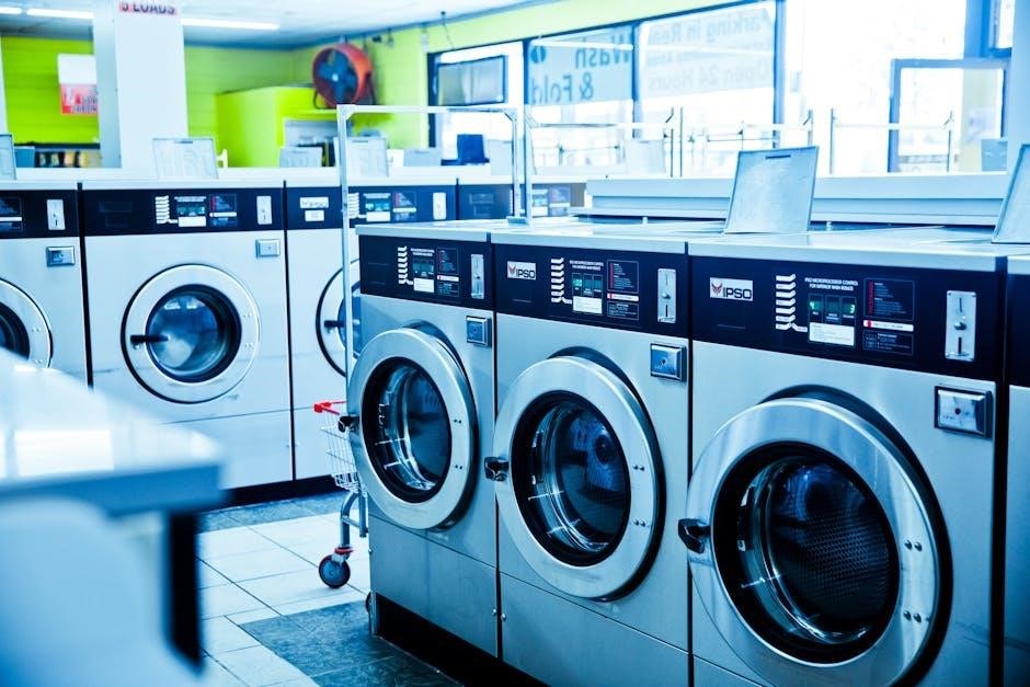
The Indesit IWDC 6125 is a freestanding washer dryer, often available in white, designed for convenient laundry care. This comprehensive guide, built upon readily available online manuals and resources like the Internet Archive and ManualsLib, aims to empower users with a thorough understanding of its features.

This appliance combines washing and drying capabilities into a single unit, saving space and streamlining your laundry routine. Multiple versions of the instruction manual are accessible online, dating back to 2020, offering consistent support. Understanding this manual unlocks masterful control and reveals hidden potential within your Indesit IWDC 6125.

Before operation, familiarize yourself with the safety precautions and machine components detailed within. This introduction sets the stage for efficient and trouble-free use, maximizing the lifespan of your appliance.

Safety Precautions

Prior to using your Indesit IWDC 6125 washer dryer, carefully review these crucial safety precautions. Disconnect the appliance from the power supply during installation, maintenance, and cleaning to prevent electrical shock. Ensure proper grounding and avoid using extension cords.

Never attempt to repair the appliance yourself; contact qualified service personnel for any repairs. Keep children and pets away from the machine during operation. Do not overload the drum, and always check pockets for foreign objects before loading laundry.

Avoid contact with water during operation and ensure adequate ventilation. Refer to the full instruction manual, available online, for a complete list of safety guidelines and warnings.

Machine Overview & Components

The Indesit IWDC 6125 is a freestanding washer dryer designed for convenient laundry care. Key components include the main drum for washing and drying, a detergent drawer for dispensing laundry products, and a control panel for selecting programs and settings.

Essential features also encompass a filter system to trap lint and debris, ensuring efficient operation and preventing blockages. The machine’s exterior features a door for loading laundry and various indicator lights to display the current cycle status.

Detailed diagrams and component locations are readily available in the comprehensive instruction manual, accessible through online resources like the Internet Archive.

Control Panel Explained

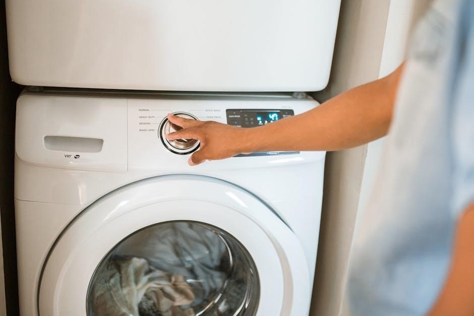
The Indesit IWDC 6125’s control panel features a dial for program selection, allowing you to choose from various wash and dry cycles. Push-buttons adjust temperature, spin speed, and additional options like delay start.

Indicator lights clearly display the selected program, cycle progress, and any active functions. Understanding these indicators is crucial for effective operation. The manual provides a detailed breakdown of each button and its corresponding function.

Masterful control is achieved by familiarizing yourself with the panel’s layout, empowering you to customize settings for optimal laundry results, as highlighted in available online guides.

Detergent Drawer Details

The Indesit IWDC 6125’s detergent drawer is typically divided into three compartments. The first, marked with “I” or a Roman numeral I, is for pre-wash detergent. The second, marked “II” or a Roman numeral II, is for main wash detergent.

The compartment often indicated with a flower symbol is for fabric softener. Always use the correct type of detergent and softener, following the manufacturer’s instructions. Overfilling can cause issues.

Regular cleaning of the detergent drawer is essential to prevent blockages and ensure optimal performance, as detailed in the user manual and online resources.

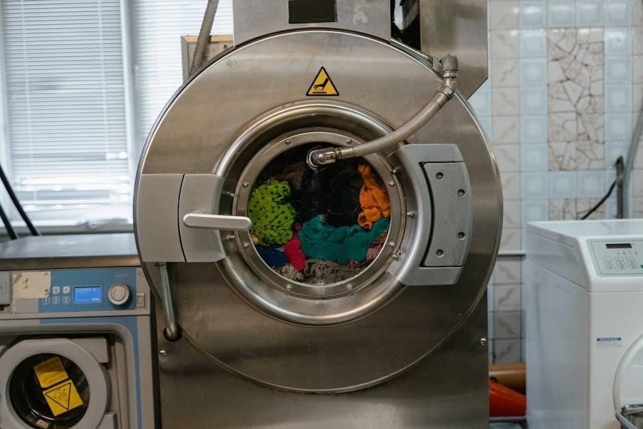
Drum and Filter Location

The stainless steel drum within the Indesit IWDC 6125 is designed for laundry loading. Accessing the drum is straightforward via the front-loading door. Regularly check for any small items left behind after cycles.

The filter, crucial for preventing blockages, is typically located behind a small access panel, often at the bottom front of the machine. Consult the manual for the precise location.

Cleaning the filter regularly – as outlined in the instruction manual – is vital for maintaining optimal drainage and preventing error codes. A blocked filter can lead to performance issues.

Getting Started: Initial Setup

Before first use, carefully remove all transit bolts from the rear of the Indesit IWDC 6125. These are essential for stabilizing the machine during transport and must be removed to prevent damage during operation.

Ensure the washer dryer is level using the adjustable feet. An uneven machine can cause excessive noise and vibration. Connect the water inlet hose securely to both the appliance and the water supply.

Verify the electrical connection meets the specified requirements. Run an initial empty cycle to flush out any manufacturing residue before loading laundry. This prepares the machine for optimal performance.

First-Time Use Instructions

Prior to the initial wash, execute a short, empty cycle using a low-temperature setting. This crucial step effectively cleans the drum and hoses, removing any residual debris from the manufacturing process.

Add a small amount of detergent – approximately one tablespoon – to the detergent drawer during this first cycle. Avoid overloading the machine; keep it empty for this initial run.

Observe the machine during operation, checking for any leaks or unusual noises. This preliminary test ensures proper functionality and safeguards against potential issues before regular use begins, guaranteeing optimal performance.

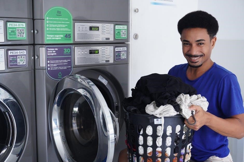
Loading Laundry Correctly

Distribute items evenly within the drum to maintain balance during the wash and spin cycles. Avoid overloading, as this can reduce cleaning effectiveness and potentially damage the machine. Consult the manual for maximum load capacities based on fabric type.

Separate laundry by fabric type, color, and washing instructions. Delicate items should be placed in a mesh laundry bag for protection. Ensure pockets are empty to prevent damage to both clothing and the appliance.

Loosely place items into the drum; do not tightly pack them. Proper loading ensures thorough cleaning and minimizes wrinkling, extending the life of your garments.

Washing Programs: A Detailed Breakdown

The Indesit IWDC 6125 offers a variety of washing programs tailored to different fabric types and soil levels. These include options for cotton, delicates, synthetics, and quick wash cycles. Each program adjusts water temperature, spin speed, and wash duration accordingly.

Program selection is crucial for optimal cleaning and fabric care. Refer to garment care labels for specific washing instructions. Utilize the program guide within the manual to understand each cycle’s parameters and ensure appropriate settings are chosen.

Adjustments can be made to temperature and spin speed for customized washing.

Cotton Wash Program Settings

The Cotton program on the Indesit IWDC 6125 is designed for durable cotton items like t-shirts, underwear, and bed linen. It offers varying intensity levels – Eco, Intensive, and Normal – to accommodate different soil levels.

Eco mode provides energy-efficient washing with a lower temperature and extended cycle duration. Intensive is ideal for heavily soiled cottons, utilizing higher temperatures and vigorous agitation. Normal offers a balanced approach for everyday cotton laundry.

Spin speed can be adjusted within the Cotton program, ranging from 400 to 1400 RPM, influencing the dryness level of the washed items.

Delicates/Silk Program Guide

The Delicates/Silk program on your Indesit IWDC 6125 is specifically engineered for fragile fabrics like silk, lace, and sheer materials. This program utilizes a gentle washing action and lower temperatures to prevent damage and maintain fabric integrity.

Always use a mild detergent formulated for delicate fabrics. Avoid overloading the drum, as this can cause excessive friction and potential tearing. Spin speed is automatically reduced on this program to minimize creasing and stretching.

Consider using a laundry bag for particularly sensitive items to provide an extra layer of protection during the wash cycle. This ensures optimal care for your delicate garments.

Synthetic Fabrics Wash Options

The Indesit IWDC 6125 offers versatile synthetic fabric wash options, catering to polyester, nylon, acrylics, and blends. These programs balance effective cleaning with fabric preservation, utilizing moderate temperatures and controlled agitation.

Select the appropriate intensity based on soiling levels – a lower intensity for lightly soiled items and a higher intensity for more stubborn stains. Temperature control is crucial; avoid excessively hot water, which can damage synthetic fibers.

Utilize the adjustable spin speed to minimize wrinkling. A lower spin speed is recommended for delicate synthetics, while a higher speed can be used for more durable fabrics. Always check garment care labels before washing.

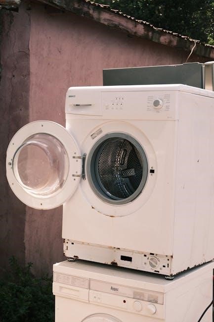
Drying Programs: Understanding Your Options

The Indesit IWDC 6125 provides a range of drying programs to suit various fabric types and desired dryness levels. These options extend beyond simple tumble drying, offering tailored cycles for optimal garment care.

Explore programs like ‘Ironing Drying,’ which leaves clothes slightly damp for easier ironing, and the ‘Tumble Dry’ setting, adjustable for different heat levels. Consider the ‘Air Refresh/Cool Down Cycle’ for a gentle refresh without heat, reducing wrinkles and odors.

Always adhere to garment care labels when selecting a drying program. Over-drying can cause shrinkage and damage, while under-drying leaves clothes damp and potentially mildewed.

Ironing Drying Program

The Ironing Drying Program on your Indesit IWDC 6125 is specifically designed to leave laundry at the ideal moisture level for ironing. This cycle reduces the time and effort required for a crisp, professional finish.

Unlike full tumble drying, this program utilizes a lower heat setting and shorter drying time, preventing over-drying and minimizing wrinkles. It’s perfect for delicate fabrics and items that require a smooth, pressed appearance.

Remember to remove items promptly after the cycle completes to prevent them from drying completely and becoming creased. This program optimizes convenience for your ironing routine.

Tumble Dry Program Settings

The Indesit IWDC 6125 offers versatile tumble dry program settings to cater to various fabric types and desired dryness levels. These settings allow for customized drying, protecting your garments.

Typically, you’ll find options like ‘High Heat’ for robust items like towels, ‘Medium Heat’ for everyday clothes, and ‘Low Heat’ or ‘Air Dry’ for delicates. Adjusting the dryness level – from ‘Very Dry’ to ‘Ironing Dry’ – further refines the cycle.

Consult your user manual for specific temperature recommendations and drying times for different fabrics. Proper setting selection ensures efficient drying and prevents damage to your laundry.

Air Refresh/Cool Down Cycle

The Indesit IWDC 6125 incorporates an Air Refresh/Cool Down cycle, a valuable feature for gently revitalizing clothes and preventing creasing after tumble drying. This cycle utilizes cool air to reduce wrinkles and static cling.

It’s particularly useful for items you intend to wear shortly, minimizing the need for ironing. The cool-down phase also ensures garments are safe to handle immediately after the drying process, preventing burns.

Refer to your appliance’s manual for the cycle’s duration and specific instructions. Utilizing this feature extends the life of your clothes and enhances convenience.

Maintenance and Cleaning

Regular maintenance is crucial for optimal performance of your Indesit IWDC 6125. Consistent cleaning prevents build-up and ensures longevity. Key areas require attention, including the detergent drawer, filter, and drum.

The detergent drawer should be removed and cleaned periodically to avoid residue accumulation. Filter cleaning is essential after each drying cycle to maintain airflow and efficiency. The drum benefits from occasional cleaning cycles.

Consult the user manual for detailed instructions on these procedures. Proper upkeep safeguards your appliance and maintains its effectiveness, ensuring years of reliable service.

Cleaning the Detergent Drawer

To clean the Indesit IWDC 6125 detergent drawer, first, locate and remove it from the machine – typically by pressing a release button or lever. Rinse the drawer thoroughly under warm running water, removing any detergent or fabric softener residue.

For stubborn build-up, use a soft brush to gently scrub the compartments. Ensure all sections, including the pre-wash, main wash, and softener compartments, are completely clear.

After cleaning, dry the drawer before reinserting it into the machine. Regular cleaning prevents blockages and ensures optimal detergent distribution during wash cycles.

Filter Cleaning Procedures

Locate the filter access panel, usually at the bottom front of the Indesit IWDC 6125. Prepare a shallow container and towels to catch any residual water. Carefully open the panel and unscrew the filter cap – water will drain, so be prepared!

Remove the filter and clean it thoroughly under running water, removing lint, fluff, and any small objects. Inspect the filter housing for debris and clear it out.

Reinstall the cleaned filter securely, ensuring the cap is tightly closed to prevent leaks. Regular filter cleaning maintains optimal performance and prevents drainage issues.

Drum Cleaning Recommendations

Maintain your Indesit IWDC 6125’s drum hygiene by performing regular cleaning cycles. Utilize a washing machine cleaner specifically designed for drum cleaning, following the product’s instructions carefully.

Alternatively, run a hot wash cycle (90°C) with a cup of white vinegar to help dissolve limescale and remove detergent residue. Ensure the drum is empty during this process.

Periodically wipe down the drum’s interior with a damp cloth to remove any lingering debris. Consistent drum cleaning prevents odors and ensures optimal washing and drying performance.

Troubleshooting Common Issues

Encountering problems? This section addresses frequent issues with your Indesit IWDC 6125. Error codes displayed indicate specific malfunctions; consult the manual for their meanings and suggested solutions.

If the machine isn’t draining, check the drain hose for kinks or blockages. Also, inspect the drain filter for obstructions. Noisy operation could stem from unbalanced loads or foreign objects within the drum.

Before seeking professional help, review the manual’s troubleshooting guide. Remember to disconnect the appliance from the power supply before any internal inspection or maintenance attempts.

Error Codes and Their Meanings

Decoding error messages is crucial for diagnosing issues with your Indesit IWDC 6125. The appliance utilizes a code system to pinpoint malfunctions, simplifying the troubleshooting process.

While specific codes vary, common errors relate to water supply, drainage problems, or issues with the heating element. The instruction manual provides a comprehensive list, detailing each code’s meaning and recommended action.

Always refer to the manual for accurate interpretations. Ignoring error codes can lead to further damage or compromise the appliance’s performance. Note the code before contacting support.

Machine Not Draining Solutions

Encountering a draining issue with your Indesit IWDC 6125? First, verify the drain hose isn’t kinked or blocked. Ensure it’s correctly positioned and free from obstructions.

Next, inspect the drain pump filter – a common culprit for blockages. Locate it (refer to the manual for its precise location) and carefully clean it, removing any debris like lint or small objects.

If the problem persists, check for clogs within the drain pump itself. Consult the manual for guidance on accessing and inspecting the pump. A professional repair may be needed if issues remain.

Noisy Operation – Identifying the Cause

Excessive noise during operation of your Indesit IWDC 6125 can stem from several sources. Ensure the machine is level; an uneven surface amplifies vibrations. Check for loose items within the drum – coins, buttons, or small objects can create rattling sounds.

Inspect the suspension rods and shock absorbers; worn components contribute to banging or thumping noises during spin cycles. A failing motor bearing can produce a grinding sound.

If the noise persists, consult a qualified technician. Attempting self-repair of internal components can be dangerous and void your warranty.

Technical Specifications

The Indesit IWDC 6125 is a freestanding washer dryer designed for domestic use. While precise dimensions aren’t universally listed, expect a standard width of approximately 60cm. Weight varies, but generally falls around 65-70kg when empty.

Electrical requirements are typically 220-240V, with a standard 10A fuse. Water consumption details depend on the selected program, but average around 49 liters for a full wash cycle. Drying capacity is approximately 7kg, while washing capacity reaches 9kg.

Please refer to the full manual for detailed specifications and energy efficiency ratings.

Dimensions and Weight

The Indesit IWDC 6125 is designed as a freestanding unit, fitting comfortably into standard laundry spaces. While exact measurements can vary slightly, the typical dimensions are approximately 85cm in height, 60cm in width, and 60cm in depth.

Its weight, when empty, is around 65-70 kilograms. This substantial weight contributes to stability during both washing and drying cycles. Consider this when positioning the appliance, ensuring the floor is level and capable of supporting the load.

Always consult the official product documentation for precise specifications before installation.

Electrical Requirements

The Indesit IWDC 6125 operates on a standard 220-240 Volt AC power supply, with a frequency of 50Hz. It’s crucial to ensure your electrical outlet meets these specifications before connecting the appliance.

A dedicated, properly grounded electrical connection is essential for safe operation. The machine typically requires a 13 Amp fuse, though this can vary depending on your region’s electrical standards.

Avoid using extension cords or adapters, as they can pose a safety hazard. Always consult a qualified electrician if you are unsure about your electrical setup.

Water Consumption Details

The Indesit IWDC 6125’s water consumption varies depending on the selected wash program and load size. A standard cotton wash cycle typically uses between 40 to 50 liters of water.

Eco programs are designed to minimize water usage, often consuming around 35-40 liters per cycle. Delicate or silk washes require less water, generally between 25 and 30 liters.

Always refer to the program guide within the appliance or the full instruction manual for precise water consumption figures for each specific wash setting. Efficient water usage contributes to environmental responsibility.

tg20 21 pdf free download

TG20:21 PDF Free Download: A Comprehensive Guide (Updated 02/16/2026)

Access Design offers a TG20:21 e-guide software download, enabling the creation of compliance sheets for scaffold construction and checking. Find the PDF and further details via NASC official sources, ensuring your scaffolding meets current guidelines.

What is TG20:21?

TG20:21 represents the latest iteration of the National Access and Scaffolding Confederation’s (NASC) comprehensive guidance for temporary scaffolding. It’s a crucial document detailing best practices for the design, erection, alteration, and dismantling of scaffolding structures within the UK construction industry. Essentially, it’s the industry standard, superseding the previous TG20:13 guidance.

This guidance isn’t simply a set of rules; it’s a detailed framework encompassing various scaffold types, including birdcage scaffolds, bridged scaffolds, and loading bays, extending even to more complex structures like chimney scaffolds. The core function of TG20:21 is to ensure the safety of both those erecting and using scaffolding, as well as the public.

A key component supporting TG20:21 is the associated e-guide software. This software facilitates the production of compliance sheets – vital documentation used to verify the correct construction and inspection of basic scaffold designs. Staying current with TG20:21 is paramount for all involved in scaffolding operations, ensuring adherence to legal requirements and promoting a safe working environment. Accessing the PDF version allows for detailed study and implementation of these critical standards;

The Importance of TG20:21 Compliance

TG20:21 compliance isn’t merely a recommendation; it’s a fundamental requirement for legal and ethical scaffolding operations within the UK. Adhering to these guidelines significantly minimizes the risk of accidents, injuries, and potential fatalities associated with scaffolding work. Non-compliance can lead to substantial fines, legal repercussions, and damage to a company’s reputation.

The guidance ensures structures are designed and erected to withstand anticipated loads and environmental factors, safeguarding workers and the public. Utilizing the TG20:21 e-guide software and generating accurate compliance sheets demonstrates a commitment to safety and due diligence.

Furthermore, compliance facilitates smoother project approvals and inspections. Clients and regulatory bodies increasingly demand evidence of TG20:21 adherence. Downloading the TG20:21 PDF and thoroughly understanding its principles is a proactive step towards creating a safer, more efficient, and legally sound scaffolding operation. Transitioning from TG20:13 is crucial, as the older standard is now outdated, and renewal subscriptions are available through the NASC ePortal.

Where to Find TG20:21 Information – NASC Official Sources

The National Access and Scaffolding Confederation (NASC) serves as the primary and most reliable source for all TG20:21 related information. Their official website provides access to the latest guidance, updates, and resources. You can directly download the TG20:21 PDF from NASC’s Free Publications Archives section.

Beyond the downloadable PDF, the NASC website hosts a wealth of supplementary materials, including Safety Reports, Critical Guidance documents, and frequently asked questions (FAQs). These resources are invaluable for understanding the nuances of the standard and ensuring correct implementation.

For direct assistance, the NASC can be contacted via phone at (44) 20 7822 7400 or through their sales email at salesnasc.org.uk. Beware of unofficial sources, as the NASC guarantees the accuracy and currency of information published on its platforms. Access Design also provides related software and guidance, but the NASC remains the definitive authority.

NASC Free Publications Archives & TG20:21 Access

The NASC (National Access and Scaffolding Confederation) offers convenient access to TG20:21 through its Free Publications Archives. This archive is a central repository for essential scaffolding guidance, ensuring professionals can readily obtain the latest standards. Downloading the TG20:21 PDF is straightforward, providing a readily available reference document.

Alongside TG20:21, the archive contains other valuable resources, including information on NASC events like the 2023 Ball and Awards, Awards Finalists details, and records from the 2022 Awards. You’ll also find links to SG6 Video resources and Scaffex24 images from various events – the Ball & Awards and Expo.

The NASC’s commitment to accessibility extends to providing Useful Links, a Privacy Policy, and clear instructions on how to Pay the NASC. This comprehensive archive is designed to support scaffolding professionals with all their information needs, centered around safe and compliant practices. Remember to always prioritize official NASC publications.

TG20:21 vs. TG20:13: Key Differences

The transition from TG20:13 to TG20:21 represents a significant update in scaffolding guidance. While both standards aim for safety, TG20:21 incorporates enhanced clarity and addresses evolving industry practices. Existing users of TG20:13 are now required to register for TG20:21, utilizing their original TG20:13 serial number – accessible via the eGuide home screen’s information icon.

A crucial point is that the complimentary access period for those who purchased TG20:13 in 2018 or earlier has expired. Continued access now necessitates a renewal subscription, obtainable through the NASC ePortal. This ensures users are working with the most current safety protocols.

Furthermore, modern construction software increasingly integrates both TG20:13 and TG20:21 modules, facilitating a smoother transition and ensuring compatibility. Understanding these differences is vital for maintaining compliance and prioritizing safety on construction sites. The shift reflects a commitment to continuous improvement within the scaffolding industry.

TG20:21 e-Guide Software: Features and Benefits

The TG20:21 e-guide software, available from Access Design, is a powerful tool designed to streamline scaffolding compliance. Its core function is the generation of compliance sheets – essential documentation for both the construction and thorough checking of fundamental scaffold structures.

This software supports a wide range of scaffold types, including birdcage scaffolds, bridged scaffolds, and loading bays, extending its utility to even chimney scaffolds. By automating the documentation process, it significantly reduces the risk of errors and ensures adherence to the latest safety standards.

The benefits extend beyond mere compliance; the e-guide enhances efficiency, saves time, and promotes a safer working environment. It provides a clear, concise record of scaffold integrity, facilitating inspections and audits. Utilizing this software is a proactive step towards responsible scaffolding practices and minimizing potential hazards on construction projects.

Compliance Sheets & Scaffold Types Supported by the e-Guide

The TG20:21 e-guide software’s primary output is comprehensive compliance sheets. These documents are crucial for demonstrating adherence to the latest scaffolding regulations and ensuring structural safety. They detail the specific configurations and checks performed on each scaffold, providing a clear audit trail.

The software boasts broad compatibility, supporting a diverse array of scaffold types. Key structures covered include birdcage scaffolds, known for their complex, cage-like structure, and bridged scaffolds, commonly used to span obstacles. It also effectively manages documentation for loading bays, vital for material handling on construction sites.

Furthermore, the e-guide extends its support to more specialized structures like chimney scaffolds, requiring careful consideration due to their height and unique challenges. By providing tailored compliance sheets for each type, the software simplifies the verification process and promotes consistent safety standards across all scaffolding operations.

Birdcage Scaffolds and TG20:21

Birdcage scaffolds, characterized by their fully enclosed, multi-level structure, demand meticulous attention to detail regarding stability and load distribution. TG20:21 provides specific guidance for the design, erection, and inspection of these complex systems, ensuring they meet stringent safety criteria.

The TG20:21 e-guide software is particularly valuable for birdcage scaffolds, generating detailed compliance sheets that document every aspect of the structure. These sheets cover crucial elements like ledger spacing, transom configuration, and the secure tying of the scaffold to a suitable structure.

Compliance with TG20:21 for birdcage scaffolds necessitates a thorough understanding of load calculations and the correct application of bracing. The e-guide assists in verifying these calculations and confirms that the scaffold is adequately braced to withstand anticipated loads, including wind and material weight. Proper planning and adherence to the guidelines are paramount for safe operation.

Bridged Scaffolds and TG20:21

Bridged scaffolds, frequently employed to overcome obstructions or span gaps, present unique engineering challenges. TG20:21 offers detailed specifications for their safe construction, emphasizing the critical importance of bridge transom design and secure connections.

The TG20:21 e-guide software proves invaluable when dealing with bridged scaffolds, facilitating the creation of precise compliance sheets. These sheets meticulously document the span lengths, transom sizes, and the load-bearing capacity of the bridge section, ensuring structural integrity.

TG20:21 guidelines mandate careful consideration of deflection and stress distribution within the bridge section. The e-guide assists in verifying these calculations, confirming that the scaffold can safely support the intended loads without exceeding permissible limits. Proper tying and bracing are also essential, and the software aids in documenting these critical safety features. Adherence to these standards is vital for preventing collapse and ensuring worker safety.

Loading Bays and TG20:21

Loading bays, crucial for material handling on construction sites, require robust scaffolding solutions. TG20:21 provides specific guidance on constructing safe and stable loading bay scaffolds, addressing the dynamic loads imposed by lifting operations and material transfer.

The TG20:21 e-guide software is particularly useful for loading bay assessments, generating compliance sheets that detail the scaffold’s capacity and limitations. These sheets must accurately reflect the maximum load allowed, considering the lifting equipment used and the distribution of weight.

TG20:21 emphasizes the need for secure guarding and edge protection on loading bays to prevent falls of persons or materials. The e-guide assists in documenting these safety measures, ensuring they meet the required standards. Proper base plate stabilization and tying to the structure are also paramount, and the software helps verify their adequacy. Regular inspections and adherence to the guidelines are essential for maintaining a safe working environment around loading bays.

Chimney Scaffolds and TG20:21 Considerations

Chimney scaffolds present unique challenges due to their height, often irregular shape, and exposure to weather. TG20:21 provides detailed guidance on safely erecting and using scaffolds around chimneys, emphasizing stability and fall protection.

The TG20:21 e-guide software is invaluable for chimney scaffold design, allowing users to generate compliance sheets that demonstrate adherence to the standard. These sheets must account for wind loading, the chimney’s condition, and the weight of materials and personnel.

TG20:21 stresses the importance of independent support for chimney scaffolds, avoiding reliance on the chimney structure itself. Careful tying and bracing are crucial, and the e-guide assists in verifying their effectiveness. Regular inspections are vital, particularly after adverse weather. Consideration must also be given to falling debris and appropriate safety netting or debris screens. Proper access and egress, including ladder positioning and guardrails, are also key components addressed by the standard.

Registering for TG20:21: Requirements & Serial Numbers

To access the full benefits of TG20:21, including the e-guide software and ongoing updates, registration through the NASC ePortal is required. This ensures users have the latest scaffolding guidance and can generate compliant compliance sheets.

For those previously using TG20:13, the registration process is straightforward, but requires your original TG20:13 serial number. This number can be located within the TG20:13 eGuide itself, accessible from the home screen via the information icon (‘i’).

It’s important to note that the complimentary access period for purchasers of TG20:13 in 2018 and earlier has expired. Continued access to TG20:21 necessitates a renewal subscription, conveniently purchased through the NASC ePortal after logging in. Ensure you have your serial number readily available to streamline the registration and subscription process, guaranteeing uninterrupted access to vital scaffolding safety resources.

TG20:13 Users: Transitioning to TG20:21

For users currently operating with TG20:13, transitioning to the updated TG20:21 guidance is crucial for maintaining compliance and ensuring scaffolding safety. While TG20:13 remains a valuable resource, TG20:21 incorporates the latest industry best practices and regulatory requirements.

The transition isn’t a complete overhaul; existing knowledge of TG20:13 provides a solid foundation. However, familiarizing yourself with the key differences between the two versions is essential. The TG20:21 e-guide software facilitates this process by offering updated compliance sheets and tools.

Remember, the free access period for early TG20:13 purchasers has concluded. To continue accessing updated guidance and software, a renewal subscription via the NASC ePortal is necessary. This ensures uninterrupted access to the latest scaffolding standards and supports ongoing safety within your operations. A smooth transition benefits everyone involved in scaffolding work.

TG20:13 Subscription Renewal & NASC ePortal

Maintaining access to vital scaffolding guidance requires understanding the TG20:13 subscription renewal process through the NASC ePortal. The complimentary period for those who purchased TG20:13 in 2018 and prior has now expired, necessitating a paid renewal to continue utilizing the software and associated resources.

The NASC ePortal serves as the central hub for managing your subscription. Logging in allows you to view your current status, initiate a renewal, and access updated software versions, including those compatible with TG20:21 functionalities. Renewal ensures continued access to critical compliance sheets and industry best practices.

Don’t risk operating with outdated information. A current subscription demonstrates a commitment to safety and adherence to the latest scaffolding standards. The NASC ePortal provides a secure and efficient method for managing your TG20:13 subscription and preparing for a seamless transition to TG20:21 when ready.

TG20:13 and TG20:21 Modules in Construction Software

Modern construction software increasingly integrates dedicated modules for scaffolding compliance, specifically supporting both TG20:13 and the updated TG20:21 standards. Global Construction Software and Services, for example, offers versions incorporating these crucial modules, streamlining the scaffolding design, erection, and inspection processes.

These modules facilitate the creation of accurate compliance sheets, essential for demonstrating adherence to safety regulations. They often feature built-in calculations and checks, reducing the risk of errors and ensuring structures meet the required specifications outlined in both TG20:13 and TG20:21.

The integration of these modules within broader construction software platforms enhances project management efficiency. It allows for seamless data sharing between teams and provides a centralized repository for all scaffolding-related documentation. Transitioning from TG20:13 to TG20:21 within these systems is often simplified through software updates and compatibility features, ensuring continued compliance and safety on construction sites.

Safety Reports and Critical Guidance Related to TG20:21

The NASC (National Access Scaffolding Confederation) prioritizes safety, providing readily available Safety Reports and Critical Guidance directly related to TG20:21 compliance. These resources are vital for staying informed about best practices and potential hazards within the scaffolding industry.

Critical Guidance documents offer detailed explanations of specific requirements outlined in TG20:21, helping scaffolders and site managers understand and implement the standards effectively. Safety Reports often detail incident investigations and lessons learned, promoting a proactive approach to risk management.

Access to these reports and guidance materials is typically available through the NASC website, alongside the TG20:21 e-guide software and associated documentation. Regularly reviewing these resources is crucial for maintaining a safe working environment and ensuring adherence to the latest scaffolding regulations. The NASC emphasizes the importance of continuous improvement and knowledge sharing within the industry, making these resources invaluable for all stakeholders.

NASC Contact Information & Sales Enquiries

For all TG20:21 related inquiries, including sales and support for the e-guide software and access to the PDF documentation, the NASC (National Access Scaffolding Confederation) is the primary point of contact. They offer comprehensive assistance to ensure seamless implementation of the latest scaffolding guidance.

You can reach the NASC sales team directly at (44) 20 7822 7400. Alternatively, for sales-specific questions and to discuss your requirements, email them at salesnasc.org.uk. Their dedicated team is equipped to handle a wide range of queries, from individual purchases to larger organizational licensing.

The NASC website also provides a detailed contact form for general inquiries and technical support. They are committed to providing prompt and efficient assistance to all members and users of TG20:21. Don’t hesitate to reach out to the NASC for clarification, guidance, or to explore how TG20:21 can benefit your scaffolding operations; They are the authoritative source for all things related to scaffolding safety and compliance.

bs 7671:2022 pdf free download

BS 7671:2022 PDF Free Download: A Comprehensive Plan

BS 7671:2022, the 18th Edition Wiring Regulations, is crucial for UK electrical professionals; accessing the official document, even with a yearly fee, ensures compliance.

Understanding BS 7671:2018 A2:2022

BS 7671:2018, amended by A2:2022, represents the current national standard for electrical installations in the UK; This isn’t merely an update; it’s a significant revision impacting design, installation, and certification processes. Understanding the nuances of this amendment is paramount for qualified electricians and anyone involved in electrical work.

The standard dictates safe practices, covering everything from earthing and bonding to circuit protection. Accessing a legitimate copy, though potentially requiring a subscription or purchase, is vital. Relying on unofficial PDFs carries substantial risks, including outdated information and potential legal ramifications. The IET provides various access options, including Bronze Packages, offering cost-effective solutions for staying current.

The Importance of the 18th Edition Wiring Regulations

The 18th Edition Wiring Regulations (BS 7671:2018 A2:2022) are not simply recommendations, but legal requirements for all electrical installations within the UK. Compliance ensures safety, minimizes risks of fire and electric shock, and protects both individuals and property. A thorough understanding is crucial for qualified electricians, designers, and building control personnel.

While seeking a BS 7671:2022 PDF might seem convenient, prioritizing official sources – like the IET website or authorized distributors – is essential; Utilizing unofficial copies introduces potential inaccuracies and legal vulnerabilities. Investing in legitimate access, even with associated costs, safeguards professional integrity and project legality.

Amendment 2:2022 – Key Changes and Updates

Amendment 2:2022 to BS 7671 introduces significant updates impacting electrical installation design, safety, and efficiency. Key areas include enhanced protection against overvoltages, increased focus on energy efficiency, and refinements to earthing and bonding practices. Understanding these changes is paramount for compliance.

Accessing a reliable BS 7671:2022 PDF – ideally through official IET channels – is vital to grasp these modifications. While free downloads may exist, they risk being outdated or inaccurate, potentially leading to non-compliant installations. Prioritize legitimate sources to ensure adherence to the latest regulations and maintain professional standards.

Where to Find Official BS 7671:2022 Documents

Obtaining official BS 7671:2022 documents is crucial for accurate and compliant electrical work. The primary source is the IET Website, offering various subscription options and digital formats. Authorized distributors and retailers also provide legitimate copies, ensuring you receive the latest amendment updates.

Beware of unofficial PDF downloads, as these may be outdated, incomplete, or infringe copyright. While the allure of a “free” download is tempting, the risks associated with non-compliant documentation far outweigh any cost savings. Invest in a verified copy to safeguard your projects and professional reputation.

IET Website and Subscription Options

The IET Website is the definitive source for BS 7671:2022. They offer a “Bronze Package” at £79 (plus VAT) annually, providing access to the regulations alongside other benefits – often cheaper than purchasing the printed version alone. Various subscription tiers cater to different needs, including options for individual users and organizations.

Digital access ensures you always have the most current version. Consider the benefits of regular updates and search functionality. Avoid relying on unofficial PDFs; the IET’s official platform guarantees compliance and supports the electrical industry’s standards.

Authorized Distributors and Retailers

Several authorized distributors and retailers offer BS 7671:2022 in various formats, including printed copies and digital access codes. RS Components, for example, lists the standard at £117.34 per unit, noting the price is indicative and subject to change. These retailers often provide competitive pricing and convenient purchasing options.

Ensure the source is officially recognized to guarantee authenticity and compliance. Purchasing from authorized channels protects against counterfeit or outdated materials. While a free PDF might seem appealing, it carries significant legal and safety risks; invest in a legitimate copy.

Cost Considerations: BS 7671:2022 Pricing

The cost of BS 7671:2022 varies depending on the format and access method. The IET offers a Bronze Package for £79 (plus VAT) annually, providing digital access, often cheaper than purchasing the printed version outright, which retails around £108. Retailers like RS Components sell the standard for approximately £117.34.

Beware of significantly lower prices, as unofficial PDFs are often illegal and unreliable. Consider the long-term value of official access, including updates and support, versus the risk of using a free, potentially non-compliant, document.

Bronze Package and Annual Fees

The IET’s Bronze Package offers a cost-effective route to accessing BS 7671:2022, priced at £79 (excluding VAT) per year. This digital subscription provides access to the regulations, often representing a saving compared to the printed version’s £108 retail price.

The annual fee grants ongoing access to updates and amendments, ensuring compliance with the latest standards. While a recurring cost, the Bronze Package delivers value for professionals needing consistent, reliable access to the wiring regulations, avoiding the risks associated with unofficial PDF downloads.

Comparing Prices from Different Sources

When seeking BS 7671:2022, price variations exist. The IET offers direct subscriptions, including the Bronze Package at £79/year (plus VAT). Authorized distributors, like RS Components, list the standard version around £117.34 per unit, though prices are indicative and subject to change.

Beware of significantly cheaper options, particularly free PDF downloads, as these often infringe copyright and may contain outdated or inaccurate information. Thoroughly evaluate the source’s legitimacy and ensure the document is officially sanctioned to avoid legal and safety risks. Prioritize reliable sources for accurate regulations.

Legal Implications of Using Unofficial PDFs

Utilizing unofficial BS 7671:2022 PDF downloads carries substantial legal risks. Copyright infringement is a primary concern, violating intellectual property rights held by the IET. Employing non-compliant documentation during electrical work can invalidate insurance, leading to significant financial liabilities in case of incidents.

Furthermore, outdated or inaccurate information within unofficial versions compromises safety and breaches legal obligations under UK electrical regulations. Qualified electricians risk prosecution and professional sanctions for non-compliance. Always obtain the standard from authorized sources to mitigate these serious legal consequences.

Copyright and Intellectual Property Concerns

BS 7671:2022 is protected by stringent copyright laws, owned and enforced by the Institution of Engineering and Technology (IET). Downloading unauthorized PDF copies constitutes a breach of these rights, potentially leading to legal action from the IET. Sharing or distributing illegally obtained documents further exacerbates the infringement.

Respecting intellectual property is paramount within the electrical industry. Utilizing legitimately purchased versions supports the ongoing development and maintenance of these vital safety standards. Opting for official sources ensures adherence to legal frameworks and demonstrates professional integrity, avoiding costly penalties.

Risks Associated with Non-Compliant Documents

Employing unofficial BS 7671:2022 PDFs introduces significant risks. These documents may contain errors, omissions, or outdated information, compromising electrical installation safety and potentially leading to dangerous situations. Non-compliance can invalidate insurance policies and result in substantial fines during inspections.

Furthermore, using inaccurate regulations can lead to incorrect designs and installations, increasing the likelihood of electrical faults, fires, and even injuries. Relying on legitimate sources, like the IET website or authorized distributors, guarantees access to the correct and current standards, safeguarding both professionals and the public.

Transitioning Between BS 7671 Editions (2018 & 2022)

When projects span multiple BS 7671 editions, clear communication is vital. Installations not reaching detailed design stage (Stage 4) must adhere to BS 7671:2018 A2:2022. Existing installations designed under the 2018 edition don’t necessarily require immediate upgrades, but amendments should be incorporated during alterations or extensions.

Understanding the changes introduced by Amendment 2:2022 is crucial for a smooth transition. Professionals must stay updated on new regulations regarding overvoltage protection, energy efficiency, and reference methods to ensure compliant and safe electrical work, regardless of the edition initially used.

Projects Straddling Multiple Editions

For projects initiated under BS 7671:2018 but continuing into 2022 and beyond, a phased approach to compliance is essential. Any electrical installation not yet at the detailed design stage (Stage 4) must be designed according to BS 7671:2018 A2:2022. This ensures the latest safety standards are implemented from the outset.

Clear documentation outlining the edition used for each phase is critical. Retroactively applying all 2022 changes to a completed design isn’t always necessary, but awareness and incorporation during modifications are vital for ongoing safety and regulatory adherence.

Design Stage Considerations (Stage 4)

Reaching Stage 4 – detailed design – necessitates full adherence to BS 7671:2018 A2:2022. This is the pivotal point where all calculations, selections of protective devices, and cable sizing must reflect the updated regulations. Ignoring the amendment at this stage introduces significant risk and potential non-compliance.

Careful review of changes, particularly regarding protection against overvoltages and energy efficiency, is paramount. Utilizing the official BS 7671 document, or a legitimate subscription, guarantees access to the most current requirements for a safe and compliant installation.

Key Areas of Change in Amendment 2:2022

Amendment 2:2022 brings substantial updates to BS 7671, demanding careful attention. Significant changes focus on enhanced protection against overvoltages, requiring revised risk assessments and potentially new protective measures. Furthermore, increased emphasis on energy efficiency and sustainable installations necessitates incorporating modern technologies and design approaches.

Understanding these key areas is vital for compliant designs. Accessing the official BS 7671:2022 document – through the IET website or authorized distributors – ensures electricians are fully informed and can implement the necessary changes effectively.

Protection Against Overvoltages

BS 7671:2022 Amendment 2 significantly revises requirements for protection against overvoltages. The updated regulations demand a more thorough risk assessment to determine the necessity of Surge Protective Devices (SPDs). This assessment must consider the installation’s location, potential exposure to lightning strikes, and the sensitivity of connected equipment.

Accessing the complete BS 7671:2022 PDF is crucial for understanding the detailed application notes and ensuring correct SPD selection and installation. Ignoring these changes could lead to non-compliance and potential safety hazards.

Energy Efficiency and Sustainable Installations

BS 7671:2022 increasingly emphasizes energy efficiency and sustainable electrical installations. The regulations now encourage the incorporation of technologies that minimize energy consumption and reduce environmental impact. This includes considerations for harmonic distortion, power factor correction, and the efficient design of lighting and heating systems.

A comprehensive understanding, readily available through the official BS 7671:2022 PDF, is vital for electrical professionals aiming to deliver installations aligned with modern sustainability goals and regulatory expectations. Proper implementation ensures long-term energy savings.

Reference Method Codes and Installation Types

BS 7671:2022 utilizes reference method codes to streamline the design and verification of electrical installations. These codes, detailed within the official PDF document, correlate specific installation types with appropriate calculation and testing methods. Understanding these codes is paramount for ensuring compliance and safety.

Appendix 4 of BS 7671:2008 provides a foundational basis, with updates in the 2022 amendment refining these methods. Accessing the complete BS 7671:2022 PDF allows professionals to accurately apply the correct reference method for each unique installation scenario.

Appendix 4 of BS 7671:2008 – A Historical Perspective

Appendix 4 of BS 7671:2008 served as a pivotal resource, establishing a framework for referencing installation methods and associated calculations. While superseded by updates in the 2018 and 2022 amendments, understanding its historical context remains valuable. The official BS 7671:2022 PDF details how these foundational principles have evolved.

It provided a structured approach to selecting appropriate methods, influencing design and verification processes. Accessing the complete document clarifies the progression from these earlier standards, ensuring a comprehensive understanding of current regulations.

Applying Reference Methods to Modern Installations

Modern electrical installations demand strict adherence to BS 7671:2022, utilizing updated reference methods for design and verification. The official BS 7671:2022 PDF outlines these methods, ensuring safety and compliance. These methods dictate calculations for voltage drop, fault protection, and other critical parameters.

Correct application, informed by the latest amendment, is paramount. The IET Wiring Regulations guide professionals in selecting the most suitable approach for each installation type, referencing tables derived from earlier versions like Appendix 4 of BS 7671:2008.

Certification and Maintenance Requirements

BS 7671:2022 places significant emphasis on thorough certification and ongoing maintenance of electrical installations. Accessing the complete BS 7671:2022 PDF is vital for understanding these requirements, ensuring installations meet current safety standards. Qualified electricians play a crucial role in initial certification, verifying compliance with the 18th Edition regulations.

Regular maintenance, documented according to BS 7671 guidelines, is essential for continued safety. This includes periodic inspections and testing, with records maintained to demonstrate adherence to the latest IET Wiring Regulations and legal obligations.

Ensuring Compliance with the Latest Regulations

Maintaining compliance with BS 7671:2022 demands diligent attention to detail and access to the official documentation. A current BS 7671:2022 PDF is paramount for electrical professionals, enabling them to design, install, and certify installations according to the newest standards. The IET Wiring Regulations are constantly evolving, making up-to-date resources essential.

Staying informed about Amendment 2:2022’s key changes, particularly regarding protection against overvoltages and energy efficiency, is critical. Utilizing official sources, like the IET website or authorized distributors, guarantees access to accurate and legally sound information.

The Role of Qualified Electricians

Qualified electricians are central to upholding BS 7671:2022 standards, requiring thorough understanding of the 18th Edition Wiring Regulations and Amendment 2:2022. Access to a reliable BS 7671:2022 PDF, obtained through legitimate channels like the IET or authorized retailers, is non-negotiable.

Their expertise ensures installations meet safety and legal requirements, demanding continuous professional development. Correct application of reference methods, particularly those outlined in Appendix 4, is vital. Competent electricians interpret and implement the regulations, guaranteeing safe and efficient electrical systems.

Impact of BS 7671:2022 on Electrical Design

BS 7671:2022 significantly impacts electrical design, particularly concerning overvoltage protection, energy efficiency, and updated earthing/bonding practices. Designers must meticulously apply the latest amendment, ensuring installations align with current regulations. Access to an official BS 7671:2022 PDF is paramount for accurate interpretation.

Changes to circuit protection requirements necessitate careful recalculations and component selection. Projects transitioning between editions require a clear understanding of applicable standards at each design stage. Utilizing a legitimate document avoids risks associated with non-compliant information, safeguarding design integrity.

Changes to Earthing and Bonding Practices

BS 7671:2022 introduces refinements to earthing and bonding, demanding designers thoroughly understand the updated regulations. Accessing a reliable BS 7671:2022 PDF is vital for interpreting these changes correctly. The amendment emphasizes improved protection against electric shock and electromagnetic compatibility.

Designers must reassess existing practices, ensuring compliance with the latest requirements for protective earth conductors and bonding arrangements. Utilizing the official document minimizes errors and ensures installations meet safety standards. Ignoring these updates could lead to non-compliance and potential hazards, highlighting the importance of accurate information.

Updates to Circuit Protection Requirements

BS 7671:2022 significantly updates circuit protection requirements, demanding meticulous attention to detail from electrical professionals. A current BS 7671:2022 PDF is essential for navigating these changes effectively. The amendment focuses on enhancing safety through improved fault protection and overcurrent device selection.

Designers must now consider updated diversity factors and cable sizing calculations, ensuring circuits are adequately protected against overload and short circuits. Access to the official document guarantees accurate interpretation of these complex rules. Non-compliance can result in dangerous installations, emphasizing the need for reliable, up-to-date information.

Future Updates and Potential Amendments

The IET continuously monitors industry trends and technological advancements, suggesting future updates to BS 7671:2022 are inevitable. Staying current requires proactive engagement with the IET and access to the latest revisions, ideally through a legitimate BS 7671:2022 PDF subscription or purchase.

Potential amendments may address emerging technologies like energy storage systems and electric vehicle charging infrastructure. Professionals must anticipate these changes and maintain a commitment to lifelong learning. Regularly checking the IET website for announcements and updates is crucial for ensuring ongoing compliance and maintaining professional competence.

Staying Current with the IET Wiring Regulations

Maintaining up-to-date knowledge of the IET Wiring Regulations, including BS 7671:2022, is paramount for all electrical professionals. The IET provides various resources, including webinars, training courses, and publications, to facilitate continuous professional development. Accessing the official BS 7671:2022 PDF – through subscription or authorized purchase – is a foundational step.

Regularly reviewing IET updates and participating in industry events ensures awareness of evolving standards and best practices. Proactive engagement with the IET community fosters a culture of safety and compliance, ultimately benefiting both professionals and the public.

Industry Trends and Regulatory Changes

The electrical industry is experiencing rapid evolution, driven by renewable energy integration, smart home technologies, and increased focus on energy efficiency. BS 7671:2022 reflects these trends, incorporating updated guidance on protection against overvoltages and sustainable installations. Staying informed about these changes is vital.

Regulatory shifts, like those implemented through the IET, demand continuous learning. Accessing the official BS 7671:2022 PDF ensures adherence to the latest legal requirements and promotes safe, compliant electrical work. Proactive adaptation to industry trends is key to professional success.

port of tyne departures today map pdf

Port of Tyne Departures Today: A Comprehensive Guide (February 16, 2026)

Today, February 16, 2026, accessing the Port of Tyne departures map is crucial for logistical planning; PDF download options offer offline viewing and updates.

Understanding the Port of Tyne

The Port of Tyne, strategically located on the River Tyne, serves as a vital gateway for trade and passenger travel in the North East of England.
Its significance extends beyond simple cargo handling, encompassing diverse operations including car transport via Tyne Car Terminal 1 (TCT 1) and cruise liner accommodations at the International Passenger Terminal.

Understanding current departures requires utilizing real-time data sources, including Marine Traffic websites and Vessel Tracking Services.
Accessing a Port of Tyne departures map – often available as a PDF download for offline use – is essential for monitoring vessel movements and estimated arrival times.
These maps provide a visual representation of ship locations and scheduled departures.

Historical Significance of the Port

The Port of Tyne’s history stretches back centuries, evolving from a Roman fort to a crucial medieval trading hub. Throughout the Industrial Revolution, it fueled regional growth with coal exports and shipbuilding.

Today, while modernized, its historical role informs current operations and logistical networks. Tracking departures – aided by resources like a Port of Tyne departures map, often available as a convenient PDF – reflects this ongoing connectivity. Accessing this information, alongside real-time vessel tracking, honors the port’s legacy as a vital trade link.

Geographical Location and Key Terminals

The Port of Tyne is strategically located on the River Tyne’s north bank, in North East England, facilitating access to both the North Sea and inland regions. Key terminals include the International Passenger Terminal, Tyne Car Terminal 1 (TCT 1), and various cargo handling facilities.

Visualizing these locations is simplified using a Port of Tyne departures map, frequently offered as a downloadable PDF. This map aids in understanding vessel movements and terminal-specific departure schedules, crucial for efficient logistics and supply chain management.

Real-Time Departure Information Sources

Several online resources provide up-to-the-minute Port of Tyne departure data. Marine Traffic websites and dedicated vessel tracking services offer real-time positions and estimated times of arrival (ETAs). However, a static Port of Tyne departures map, often available as a PDF, complements this dynamic data.

The PDF map provides a visual overview of terminal locations and scheduled departures, useful for planning. While not real-time, it’s a valuable supplement, especially when combined with live tracking information for comprehensive situational awareness.

Marine Traffic Websites

Marine Traffic websites are premier sources for tracking vessel movements at the Port of Tyne. These platforms display real-time positions of ships, including those preparing for departure. While not directly offering a Port of Tyne departures map in PDF format, they provide detailed information;

Users can view vessel names, IMO numbers, departure times, and ETAs. Combining this data with a separately sourced PDF map of the port’s terminals offers a comprehensive overview for logistics and planning purposes, enhancing situational awareness.

Vessel Tracking Services

Vessel tracking services complement Marine Traffic in monitoring Port of Tyne departures. These services provide detailed vessel information, including current location, speed, and destination, aiding in predicting departure times. Though a dedicated Port of Tyne departures map in PDF isn’t typically offered directly, these tools are invaluable.

Integrating data from these services with a PDF version of the port’s layout allows for precise tracking of vessels leaving specific terminals. This combination enhances logistical efficiency and provides a clear visual representation of ship movements.

Accessing the Port of Tyne Departures Map

Currently, a dedicated, regularly updated Port of Tyne departures map in PDF format isn’t readily available directly from the port authority. However, utilizing online interactive maps, combined with screenshots saved as PDFs, offers a workaround. These maps visually represent vessel locations and scheduled departures.

Checking industry websites and maritime publications may occasionally yield downloadable PDF versions of port layouts. Regularly monitoring these sources is key. Remember to verify the date of any PDF to ensure its information remains current and accurate for February 16, 2026.

Online Interactive Maps

Marine Traffic and Vessel Tracking Services provide dynamic, real-time Port of Tyne departure visualizations. These platforms display vessel positions, names, departure times, and estimated times of arrival (ETAs) on an interactive map. Users can zoom, pan, and filter vessels to focus on specific terminals.

While not a static PDF, these maps offer the most up-to-date information. Taking screenshots of these maps and saving them as PDF documents allows for offline access and record-keeping. Regularly refresh the map for the latest departure data on February 16, 2026.

PDF Download Options (Availability & Updates)

Currently, the Port of Tyne does not offer a regularly scheduled, official PDF download of its departure map. However, users can create their own PDF versions by utilizing browser “print to PDF” functions from the online interactive maps.

These self-generated PDFs require manual updates to remain current. Departure information changes rapidly, so frequent refreshes and re-saving are essential, especially on February 16, 2026. Check the official Port of Tyne website for any future announcements regarding downloadable PDF options.

Decoding the Departure Information

Understanding the data presented on the Port of Tyne departures map is vital. Key identifiers include vessel names and unique IMO numbers, essential for tracking specific ships on February 16, 2026. Departure times are listed alongside Estimated Times of Arrival (ETAs) at their next port.

Pay close attention to any flags or symbols indicating potential delays or changes. Cross-referencing this information with vessel tracking services provides a comprehensive overview of each ship’s journey.

Vessel Names and IMO Numbers

Each vessel departing the Port of Tyne on February 16, 2026, is uniquely identified. The vessel name provides a common reference point, while the IMO number – a seven-digit code – offers definitive identification. This number is crucial for accurate tracking and data correlation, especially when consulting the departures map PDF.

Utilizing both identifiers ensures clarity and avoids confusion, particularly with ships sharing similar names. These details are fundamental for logistics, freight forwarding, and monitoring vessel movements.

Departure Times and Estimated Times of Arrival (ETAs)

Accurate departure times are vital when referencing the Port of Tyne departures map PDF on February 16, 2026. These times indicate when a vessel leaves the terminal, influencing logistical planning. Estimated Times of Arrival (ETAs) provide projected arrival dates at the destination port, factoring in distance and speed.

However, ETAs are subject to change due to weather or operational delays. Regularly updating information from the map PDF ensures informed decision-making for supply chain management and freight forwarding.

Key Terminals and Their Departures

The Port of Tyne features several key terminals, each with distinct departure patterns viewable on the February 16, 2026, departures map PDF. The International Passenger Terminal handles cruise liners and ferries, while Tyne Car Terminal 1 (TCT 1) specializes in vehicle transport.

Checking the map PDF reveals specific vessel departures from each terminal, including vessel names, destinations, and scheduled times. This detailed information is crucial for tracking cargo and passenger movements, optimizing logistics, and ensuring efficient port operations.

International Passenger Terminal Departures

The International Passenger Terminal’s February 16, 2026, departures, detailed on the map PDF, primarily involve passenger ships and cruise liners. Marella Cruises utilizes this terminal, benefiting from new baggage handling facilities.

The PDF map displays scheduled departure times, vessel names, and destinations for these passenger vessels. Real-time updates, accessible through linked services, complement the static map information. This terminal’s departures are vital for tourism and regional connectivity, with the map PDF serving as a key planning resource.

Tyne Car Terminal 1 (TCT 1) Departures

The Tyne Car Terminal 1 (TCT 1) PDF map, updated for February 16, 2026, details vehicle carrier departures, notably to NLAMS. Information includes IMO numbers – like 9150339 – alongside arrival, move, and sail departure statuses.

This map PDF is essential for tracking automotive logistics. Agent Nissan coordinates many shipments. Accessing the map, alongside the Port of Tyne’s website, provides a comprehensive overview of TCT 1’s activity. Real-time data integration enhances the map’s utility for supply chain management.

Types of Vessels Departing from the Port of Tyne

The February 16, 2026, Port of Tyne departures map PDF showcases diverse vessel traffic. Cargo ships and freight vessels dominate, alongside passenger ships and cruise liners utilizing the International Passenger Terminal.

Vehicle carriers, departing from Tyne Car Terminal 1 (TCT 1), are prominently featured. The map details IMO numbers for identification. PDF accessibility allows offline viewing of scheduled departures. Real-time data integration enhances the map’s accuracy, providing crucial insights for logistics and maritime operations.

Cargo Ships and Freight Vessels

The Port of Tyne departures map PDF, dated February 16, 2026, highlights numerous cargo ships and freight vessels. These vessels transport diverse goods, impacting supply chain management. The map details destinations, often international, and provides estimated times of arrival (ETAs).

PDF accessibility allows offline tracking of these crucial shipments. IMO numbers facilitate vessel identification; Real-time updates, integrated into the map, ensure accuracy. Logistics professionals utilize this information for freight forwarding and optimizing operational efficiency, viewing detailed departure schedules.

Passenger Ships and Cruise Liners

The February 16, 2026, Port of Tyne departures map PDF showcases scheduled passenger ship and cruise liner departures. Marella Cruises utilizes the International Passenger Terminal, as noted in reports. The map details vessel names, departure times, and destinations, crucial for passenger travel planning.

PDF format enables convenient access to this information. Real-time updates reflect any schedule changes. The map aids in baggage handling logistics, a recent port improvement. Accessing this data optimizes passenger flow and ensures smooth embarkation/disembarkation processes, enhancing the overall cruise experience.

Factors Affecting Departure Schedules

The February 16, 2026, Port of Tyne departures map PDF doesn’t inherently display dynamic factors impacting schedules. However, understanding these is vital. Weather conditions and tidal influences frequently cause delays, as do potential port congestion issues.

Operational delays, though not shown on the static map, are a reality. The PDF serves as a baseline, but real-time vessel tracking services provide updates reflecting these variables. Checking both the map and live data ensures accurate logistical planning, mitigating disruptions caused by unforeseen circumstances affecting departure times.

Weather Conditions and Tidal Influences

The Port of Tyne departures map PDF, dated February 16, 2026, doesn’t dynamically reflect weather or tides. However, these significantly impact schedules. Strong winds, fog, and storms can delay or reroute vessels.

Tidal ranges at the Port of Tyne are substantial, influencing vessel access and departure windows. Lower tides may restrict larger ships. While the PDF provides a snapshot, consulting real-time weather forecasts and tidal charts alongside the map is crucial for accurate predictions and logistical adjustments, ensuring safe and efficient operations.

Port Congestion and Operational Delays

The Port of Tyne departures map PDF, as of February 16, 2026, displays scheduled departures but doesn’t account for unforeseen congestion. Increased vessel traffic, particularly at Tyne Car Terminal 1, can cause delays.

Operational issues – equipment malfunctions, staffing shortages, or customs inspections – also contribute to schedule disruptions. While the map offers a baseline, real-time vessel tracking services and port updates are essential. These provide a more accurate picture of potential delays, allowing for proactive adjustments to supply chain management and freight forwarding plans.

Utilizing Departure Information for Logistics

The Port of Tyne departures map PDF, updated as of February 16, 2026, is a foundational tool for logistics professionals. Integrating this data with real-time tracking enhances supply chain visibility.

Freight forwarders leverage departure times to optimize shipping routes and anticipate arrival dates. Accurate ETAs, derived from the map and live vessel data, minimize delays and reduce storage costs. Efficient logistics depend on proactively managing potential disruptions, informed by both scheduled and actual departure information, ensuring smooth cargo flow.

Supply Chain Management

The Port of Tyne departures map PDF, current as of February 16, 2026, is integral to robust supply chain management. Utilizing scheduled departures allows for proactive inventory planning and resource allocation.

Access to this information minimizes disruptions by enabling timely adjustments to transportation schedules. Integrating the map’s data with broader supply chain systems improves forecasting accuracy and reduces potential bottlenecks. Effective management relies on anticipating vessel movements, optimizing warehouse operations, and ensuring seamless product delivery.

Freight Forwarding and Shipping

The Port of Tyne departures map PDF, updated today, February 16, 2026, is a vital tool for freight forwarders and shipping companies. Real-time departure data streamlines operations, enabling precise shipment tracking and efficient route planning.

Accessing this information facilitates proactive communication with clients regarding estimated times of arrival. Utilizing the map’s details allows for optimized cargo consolidation and reduced demurrage costs. Accurate departure schedules are essential for coordinating onward transportation and ensuring timely delivery of goods.

COVID-19 Related Updates and Impacts on Departures

The Port of Tyne departures map PDF, as of February 16, 2026, reflects any ongoing COVID-19 related protocols impacting vessel schedules. While restrictions have largely eased, potential crew change requirements or localized outbreaks may cause unforeseen delays.

Users should consult the map alongside official Port of Tyne advisories for the latest information. The PDF provides a snapshot of current operational status, helping stakeholders anticipate potential disruptions and adjust logistics accordingly. Monitoring updates remains crucial for smooth shipping operations.

Future Developments at the Port of Tyne (2026 Outlook)

The Port of Tyne departures map PDF will integrate enhanced real-time data feeds throughout 2026, improving predictive accuracy for vessel arrivals and departures. Planned terminal expansions, particularly at Tyne Car Terminal 1, will be visually represented on updated map versions.

Digitalization efforts will prioritize a more interactive PDF experience, allowing users to filter departures by vessel type and destination; Expect improved accessibility and a streamlined interface, supporting efficient supply chain management and informed decision-making.

Resources for Further Information

For the Port of Tyne departures map PDF and related data, the official Port of Tyne website remains the primary source. Regularly check for updated versions and interactive map links. Industry publications like Maritime Executive and Lloyd’s List often feature articles on port developments.

Marine traffic websites provide supplementary vessel tracking information. Utilize these resources alongside the official PDF to gain a comprehensive understanding of current departures. Remember to verify data accuracy across multiple sources for optimal logistical planning.

Official Port of Tyne Website

The official Port of Tyne website is the definitive source for the most current departures map PDF and real-time vessel schedules. Navigate to the ‘Shipping’ or ‘Vessel Traffic’ section to locate downloadable maps and interactive tracking tools;

Expect frequent updates reflecting operational changes and potential delays. The website also provides crucial contact information for agents and terminal operators. Regularly consulting this resource ensures access to the most accurate and reliable information regarding vessel departures from the Port of Tyne.

Industry News and Maritime Publications

Several industry news sources and maritime publications often feature updates on Port of Tyne operations, including potential disruptions impacting departure schedules and map availability. Publications like Lloyd’s List and TradeWinds may offer insights beyond the official departures map PDF.

These resources can provide context regarding weather-related delays or port congestion. Regularly monitoring these channels, alongside the official Port of Tyne website, offers a comprehensive understanding of vessel movements and potential impacts on logistics planning.

manual handling risk assessment example

Manual handling risk assessments are crucial for workplace safety‚ aligning with regulations like MHOR 1992 and AS45001:2018.
These assessments systematically identify and mitigate hazards associated with lifting‚ carrying‚ and repetitive movements‚ ensuring employee wellbeing.

Purpose of the Assessment

The primary purpose of a manual handling risk assessment is to proactively protect employees from musculoskeletal disorders (MSDs) arising from hazardous manual tasks. This assessment isn’t merely a compliance exercise‚ dictated by regulations like the Manual Handling Operations Regulations 1992 (MHOR)‚ but a fundamental commitment to worker health and safety.

Specifically‚ the assessment aims to identify tasks that present a risk‚ evaluate the level of that risk considering factors like load weight and posture‚ and then implement appropriate control measures. These measures‚ guided by the hierarchy of control‚ prioritize eliminating risks where possible‚ followed by reducing them through engineering or organizational changes.

A well-conducted assessment provides a documented record of identified hazards‚ the risks they pose‚ and the controls in place‚ facilitating continuous improvement and demonstrating due diligence. Ultimately‚ it strives to create a safer working environment‚ minimizing the incidence of work-related injuries and promoting employee wellbeing.

Legal Requirements (MHOR 1992)

The Manual Handling Operations Regulations 1992 (MHOR) place a clear legal duty on employers to manage the risks of manual handling in the workplace. Regulation 4(1) of MHOR establishes a hierarchy of measures to control these risks‚ prioritizing elimination of hazardous tasks whenever reasonably practicable.

Employers are legally obligated to assess manual handling risks‚ taking into account factors like load weight‚ frequency‚ posture‚ and individual capabilities. This assessment must be documented‚ and the findings communicated to employees. Furthermore‚ MHOR requires employers to provide information‚ instruction‚ and training to ensure employees can handle loads safely.

Failure to comply with MHOR can result in enforcement action by the Health and Safety Executive (HSE)‚ including improvement notices or prosecution. A robust manual handling risk assessment process is‚ therefore‚ not only best practice but a legal necessity for protecting employees and avoiding potential penalties.

Scope of this Example Assessment

This example manual handling risk assessment is designed to be a broadly applicable template‚ adaptable to various workplace scenarios. It focuses on identifying hazards associated with common manual handling tasks‚ such as lifting‚ lowering‚ carrying‚ pushing‚ and pulling of loads. The assessment considers factors outlined in MHOR 1992 and aligns with AS45001:2018 standards.

The scope encompasses a detailed task description‚ including load characteristics (weight‚ dimensions)‚ frequency of handling‚ carrying distances‚ and observed postures. It also includes an evaluation of existing control measures and proposes additional controls based on the hierarchy of control. This assessment is intended to be a living document‚ regularly reviewed and updated.

Specifically‚ it aims to identify those at risk from manual handling injuries and to provide a clear record of the assessment findings. While comprehensive‚ it’s crucial to remember that this is an example; each workplace requires a tailored assessment reflecting its unique operations and risks.

Identifying Manual Handling Activities

Identifying tasks involving lifting‚ carrying‚ and repetitive movements is the first step. This includes documenting operations‚ load details‚ and potential hazards for a thorough risk assessment.

Defining Manual Handling

Manual handling‚ as defined by the Manual Handling Operations Regulations 1992 (MHOR)‚ encompasses any transporting or supporting of a load by hand or bodily force. This extends beyond simply lifting and lowering; it includes activities like carrying‚ pushing‚ pulling‚ twisting‚ bending‚ and even holding items;

Crucially‚ it considers the risk of injury‚ not just the weight or awkwardness of the load. A seemingly light box can pose a significant risk if lifted repeatedly or in a poor posture. The assessment process must therefore consider the entire task‚ from start to finish.

This definition is broad‚ covering a wide range of workplace activities. Recognizing this breadth is essential for a comprehensive risk assessment. It’s not limited to warehouse environments; manual handling can occur in offices‚ healthcare settings‚ and construction sites‚ among others. Accurate identification of these activities is the foundation of effective risk management.

Common Tasks Requiring Assessment

Numerous workplace tasks routinely necessitate a manual handling risk assessment. These include lifting and lowering boxes‚ bags‚ or other materials – a staple in warehousing and retail. Manually transferring patients in healthcare settings presents high risks due to the vulnerability of those involved and often awkward postures.

Construction sites frequently require assessments for tasks like carrying building materials‚ digging‚ and moving heavy tools. Office environments aren’t exempt; repetitive paper handling‚ moving equipment‚ and even prolonged static postures can contribute to musculoskeletal disorders.

Other common examples encompass loading and unloading vehicles‚ stacking shelves‚ assembling products‚ and waste disposal. Any task involving the physical exertion of moving or supporting a load should be scrutinized. A proactive approach to identifying these tasks is vital for preventing injuries and ensuring a safe working environment.

Site/Location of Task Documentation

Maintaining readily accessible documentation is paramount for effective manual handling risk management. Records of completed assessments‚ including detailed task descriptions and identified control measures‚ should be stored both electronically and in a physical format.

A central location‚ such as a designated safety folder within a shared network drive‚ ensures all relevant personnel can easily access the information. Hard copies should be kept in a clearly labelled file‚ ideally near the task location itself – for example‚ in a supervisor’s office or on a notice board within the department.

The documentation must clearly list those at risk‚ detailing specific roles and individuals potentially exposed to hazards. Regular audits should verify the documentation’s completeness and accessibility. This systematic approach supports ongoing monitoring and continuous improvement of manual handling safety protocols.

Assessing the Risks: Hazard Identification

Hazard identification involves evaluating load weight‚ carrying distances‚ postures‚ frequency‚ and repetitive movements. These factors‚ alongside workplace conditions‚ determine potential manual handling risks.

Load Weight & Dimensions

Assessing load weight and dimensions is fundamental to manual handling risk assessments. Heavier loads inherently pose a greater risk of injury‚ particularly to the back. The assessment must detail the actual weight of the item being handled‚ not just an estimate. Consider awkward shapes and sizes; bulky or unwieldy loads disrupt balance and increase strain;

Dimensions impact grip and maneuverability; Large items may obstruct vision‚ increasing the risk of collisions or trips. Irregularly shaped loads can be difficult to hold securely‚ leading to drops or muscle strains. Documentation should include precise weight measurements and detailed descriptions of the load’s dimensions.

Furthermore‚ consider whether the load’s center of gravity is offset‚ requiring additional effort to control. The assessment should also note if the load is unstable or likely to shift during handling. Accurate documentation of these factors is vital for effective risk control.

Frequency and Duration of Lifting

Evaluating lifting frequency and duration is critical in a manual handling risk assessment. Frequent lifting‚ even of relatively light loads‚ can lead to cumulative strain and musculoskeletal disorders. The assessment must quantify how often lifting occurs over a specific period – per hour‚ per shift‚ or per day. Consider both routine and occasional lifting tasks.

Prolonged lifting or carrying‚ even if infrequent‚ significantly increases risk. Sustained muscle exertion leads to fatigue‚ reducing control and increasing the likelihood of injury. Document the duration of each lifting activity and any periods of sustained carrying.

Assess whether there are sufficient rest breaks to allow for muscle recovery. A high frequency combined with long duration demands immediate attention and control measures. Detailed records of these factors are essential for prioritizing risk reduction strategies and protecting worker health.

Carrying Distance

Assessing carrying distance is a vital component of a thorough manual handling risk assessment. Longer carrying distances significantly increase the physical demands on workers‚ elevating the risk of fatigue and injury. The assessment should accurately measure the distance loads are carried‚ considering both horizontal and vertical travel.

Evaluate whether the carrying path is clear of obstructions‚ uneven surfaces‚ or other hazards that could contribute to slips‚ trips‚ or falls. Consider if the load obstructs the carrier’s vision‚ further increasing risk. Frequent or prolonged carrying over extended distances demands careful scrutiny.

Document any changes in elevation during carrying‚ as ascending or descending stairs adds substantial strain. Control measures should focus on minimizing carrying distances whenever possible‚ utilizing mechanical aids‚ or redesigning tasks to reduce the physical burden on employees.

Posture During Lifting/Carrying

Evaluating posture during lifting and carrying is paramount in a manual handling risk assessment. Poor posture dramatically increases the strain on the musculoskeletal system‚ heightening injury risk. Assess whether workers are bending‚ twisting‚ or reaching while handling loads – these positions are particularly hazardous.

Observe if the load is held close to the body‚ maintaining a stable center of gravity. A load held away from the body significantly increases stress on the back and shoulders. Note any awkward postures adopted due to space constraints or load characteristics.

Consider the height from which loads are lifted and to which they are placed. Lifting from floor level or above shoulder height presents greater challenges. Control measures should prioritize maintaining neutral postures‚ providing adequate space‚ and utilizing lifting aids to minimize awkward movements.

Repetitive Movements

Repetitive movements are a significant risk factor in manual handling assessments‚ often leading to upper limb disorders (ULDs) and musculoskeletal injuries. Evaluate tasks involving repeated lifting‚ lowering‚ carrying‚ twisting‚ or reaching motions. Consider the frequency and duration of these movements – higher repetition and longer durations increase risk.

Assess the speed of movements; faster‚ forceful repetitions are more likely to cause strain. Observe if movements are combined with awkward postures or forceful exertions‚ compounding the risk. Look for tasks lacking sufficient recovery time between repetitions.

Control measures should focus on reducing repetition through job rotation‚ task variation‚ or automation. Implementing rest breaks and promoting proper technique can also mitigate risks. Ergonomic assessments can identify opportunities to redesign tasks and minimize repetitive strain.

Risk Evaluation & Control Measures

Risk evaluation involves reviewing existing controls and applying the MHOR 1992 hierarchy – elimination‚ reduction via engineering/organisational changes – to minimize identified manual handling hazards.

Existing Control Measures Review

Before implementing new controls‚ a thorough review of existing measures is paramount. This involves documenting what is currently in place to manage manual handling risks within the specific task or location. Consider if current procedures‚ such as provided equipment‚ training programs‚ or work rotation schedules‚ are effectively reducing risk exposure.

Assess the adequacy of these existing controls. Are they consistently followed by all personnel? Is the equipment well-maintained and fit for purpose? Are employees adequately trained on proper lifting techniques and the use of available aids? Document any gaps or deficiencies identified during this review process.

This review should also encompass an examination of incident reports and near-miss occurrences related to manual handling. Analyzing these events can reveal recurring issues or weaknesses in existing controls‚ providing valuable insights for improvement. The findings of this review will inform the selection and implementation of appropriate additional control measures‚ prioritizing those higher up the hierarchy of control.

Hierarchy of Control (MHOR 1992)

The Manual Handling Operations Regulations 1992 (MHOR) establish a clear hierarchy of control measures to minimize risks. Elimination – removing the hazardous task entirely – is the most effective‚ though often challenging. If elimination isn’t feasible‚ reduction becomes the focus.

Engineering controls involve modifying the workplace or equipment. Examples include using mechanical aids like hoists or trolleys‚ adjusting workstation heights‚ or redesigning layouts to reduce carrying distances. These aim to change the task itself‚ lessening the physical demands.

Organizational controls focus on how work is done. This includes implementing safe systems of work‚ providing adequate training‚ rotating tasks to reduce repetition‚ and ensuring sufficient rest breaks. These controls rely on changing employee behavior and work practices. Personal Protective Equipment (PPE)‚ while sometimes used‚ is considered the least effective control and should only be implemented as a last resort‚ alongside other measures.

Elimination of Hazardous Tasks

Elimination represents the most effective strategy within the MHOR 1992 hierarchy of controls‚ aiming to completely remove manual handling risks. This involves fundamentally altering processes to avoid the need for lifting‚ carrying‚ or repetitive movements altogether. Consider if the task is truly necessary; can it be avoided entirely?

Practical examples include redesigning a workflow to deliver materials directly to the point of use‚ negating the need for manual transport. Automation‚ such as utilizing conveyors or robotic systems‚ can replace physically demanding tasks. Rethinking packaging – switching to smaller‚ lighter units – can also eliminate high-risk lifts.

Successfully eliminating a task requires a thorough review of existing procedures and a willingness to embrace innovative solutions. While often the most challenging option to implement‚ the long-term benefits – reduced injury risk and improved employee wellbeing – are substantial. Prioritizing elimination demonstrates a proactive commitment to safety.

Reduction of Risk – Engineering Controls

Engineering controls focus on modifying the workplace or equipment to reduce manual handling risks‚ falling second in the MHOR 1992 hierarchy. These are physical changes that minimize exposure to hazards‚ rather than relying on worker behavior. Examples include installing adjustable work platforms to reduce reaching and bending‚ or providing mechanical aids like hoists‚ trolleys‚ and pallet trucks.

Consider implementing lifting tables to bring loads to a safer working height‚ minimizing strain on the back. Redesigning layouts to shorten carrying distances is another effective engineering control. Utilizing height-adjustable workstations allows employees to adapt the environment to their individual needs‚ promoting better posture.

These controls require investment but offer a reliable and sustainable solution. Regular maintenance of equipment is crucial to ensure continued effectiveness. Engineering controls should be implemented after exploring elimination options‚ creating a safer and more efficient work environment.

Reduction of Risk – Organisational Controls

Organisational controls‚ the third tier in the MHOR 1992 hierarchy‚ involve changes to work practices and procedures to minimize manual handling risks. These focus on how tasks are performed‚ rather than altering the physical environment or equipment. Implementing a robust rotation system can reduce repetitive strain injuries by varying tasks throughout the day.

Providing comprehensive training on safe lifting techniques‚ proper posture‚ and the use of available aids is paramount. Clear Standard Operating Procedures (SOPs) detailing safe manual handling practices for each task are essential. Encouraging early reporting of discomfort or pain allows for prompt intervention and prevents escalation of issues.

Optimizing workload distribution and minimizing unnecessary carrying distances also fall under organizational controls. Regular breaks and promoting a culture of safety awareness are vital components. These controls rely on employee participation and commitment to safe work practices.

Documentation & Review

Detailed records of assessment findings‚ including identified risks and control measures‚ are essential. Regular reviews – at least annually‚ or after changes – ensure continued effectiveness and compliance.

Recording Assessment Findings

Comprehensive documentation is paramount for a robust manual handling risk assessment. The assessment record should meticulously detail the specific tasks analyzed‚ including a clear description of the operations covered – load weights‚ lifting frequencies‚ and carry distances. Visual aids‚ such as diagrams or photographs‚ significantly enhance understanding and clarity.

Crucially‚ the record must outline all existing control measures currently in place. This includes any equipment used‚ training provided‚ or procedural changes implemented to minimize risk. Furthermore‚ the assessment should clearly identify the specific hazards associated with each task‚ detailing the potential for harm.

The risk level – often categorized as low‚ medium‚ or high – must be explicitly stated for each identified hazard. Finally‚ the proposed control measures‚ designed to reduce or eliminate the risks‚ should be thoroughly documented‚ along with assigned responsibilities and timelines for implementation. This detailed record serves as a vital reference point for ongoing monitoring and review.

Identifying Those at Risk

Accurate identification of individuals potentially exposed to manual handling risks is a critical step. This extends beyond those directly performing lifting or carrying tasks. Consider employees involved in assisting with loads‚ supervising operations‚ or even those working in proximity to manual handling activities.

The assessment should specifically list job roles or departments where manual handling is prevalent. It’s vital to include temporary staff‚ contractors‚ and new employees undergoing training‚ as they may lack experience and be more vulnerable.

Particular attention should be given to individuals with pre-existing health conditions‚ such as musculoskeletal disorders or pregnancy‚ as these factors can increase their susceptibility to injury. Documenting the number of employees at risk‚ and their specific roles‚ provides a clear understanding of the scope of potential harm and informs the prioritization of control measures. This detailed list ensures targeted interventions and effective risk management.

Review Date & Process

Regular review of the manual handling risk assessment is paramount‚ ensuring its continued relevance and effectiveness. A formal review should be conducted at least annually‚ or more frequently if significant changes occur – such as alterations to tasks‚ equipment‚ or the work environment;

The review process should involve consultation with employees who perform the assessed tasks‚ gathering their feedback on the practicality and effectiveness of existing control measures. Documented changes‚ including updates to hazard identification‚ risk evaluation‚ and control strategies‚ are essential.

The assessment should also be reviewed following any incidents or near misses involving manual handling‚ to identify potential weaknesses in the current controls. A clear record of review dates‚ participants‚ and any resulting actions must be maintained‚ demonstrating a proactive approach to risk management and a commitment to employee safety. This iterative process ensures ongoing improvement.

AS45001:2018 Alignment

Alignment with AS45001:2018‚ the Australian Standard for occupational health and safety management systems‚ demonstrates a commitment to best practice. This standard emphasizes a risk-based approach‚ requiring organizations to proactively identify hazards‚ assess risks‚ and implement controls.

A comprehensive manual handling risk assessment‚ as outlined in this document‚ directly supports AS45001:2018 requirements. Specifically‚ it contributes to fulfilling obligations related to hazard identification (clause 6.1.2.1)‚ risk assessment (clause 6.1.2.2)‚ and control of risks (clause 8.1.3).

Documentation of the assessment process‚ including findings and control measures‚ provides evidence of compliance. Furthermore‚ the regular review process ensures continuous improvement‚ a key principle of AS45001:2018. Utilizing a template broadly aligned with this standard streamlines the process and demonstrates a robust safety management system.

triton t80 easi-fit manual

Triton T80 Easi-Fit Manual: An Overview

This manual details the Triton T80 Easi-Fit shower installation‚ operation‚ and maintenance. It covers safety‚ troubleshooting‚ and technical specifications for optimal performance.

The Triton T80 Easi-Fit is a popular electric shower known for its reliable performance and straightforward installation. Designed for homes with varying water pressure systems‚ this shower offers a convenient and efficient showering experience. This manual provides comprehensive guidance‚ ensuring a safe and successful setup.

Understanding the components and following the instructions carefully are crucial. The Easi-Fit model prioritizes ease of use‚ allowing for a relatively quick installation process compared to more complex systems. It’s a cost-effective solution for upgrading your bathroom‚ delivering consistent hot water on demand.

Key Features and Benefits

The Triton T80 Easi-Fit boasts several key features enhancing the showering experience. These include a high-efficiency electric heating system‚ providing rapid heat-up times and consistent temperature control. Its compact design makes it suitable for various bathroom sizes‚ while the adjustable pressure settings cater to individual preferences.

Benefits extend to simplified installation‚ reducing plumbing and electrical complexities. The unit’s robust construction ensures durability and longevity. Furthermore‚ the Easi-Fit model offers a cost-effective solution for hot water‚ minimizing energy consumption. It’s a user-friendly shower delivering performance and convenience.

Installation Process

Proper installation is crucial for safe and efficient operation. This section guides you through unboxing‚ water and electrical connections‚ and secure mounting procedures.

Unboxing and Component Check

Carefully unpack the Triton T80 Easi-Fit shower kit and verify all components are present. The box should contain the shower unit itself‚ the wall mounting bracket‚ the showerhead and hose‚ and all necessary fixings – screws‚ wall plugs‚ and washers.

Inspect each item for any signs of damage during transit. Check the shower unit’s casing for cracks or dents. Ensure the showerhead and hose are free from kinks or defects. A detailed parts list is usually included within the packaging; cross-reference this with the contents to confirm everything is accounted for before proceeding with the installation. Retain the packaging for potential returns or warranty claims.

Preparing the Water Supply

Before installation‚ ensure your water supply is compatible with the Triton T80 Easi-Fit; It requires both hot and cold water supplies at equal pressure‚ ideally between 1.0 and 5.5 bar. If your water pressure exceeds 5.5 bar‚ a pressure reducing valve must be installed.

Isolate the water supply to the existing shower. Flush the pipework to remove any debris or stagnant water. Ensure the hot and cold water inlets are clearly identified. Use appropriate plumbing fittings and sealant to create watertight connections. Consider installing filters to prevent scale buildup and protect the shower unit.

Connecting to the Mains Electricity

Electrical installation must be performed by a qualified electrician‚ adhering to current regulations. The Triton T80 Easi-Fit requires a 45A circuit breaker and a suitable cable (typically 6mm²). Always isolate the electrical supply before commencing any work.

Ensure the shower unit is correctly earthed. Connect the cable to the designated terminals within the shower’s enclosure‚ following the wiring diagram provided. Double-check all connections are secure and properly insulated. After connection‚ test the circuit breaker and verify correct operation before restoring the water supply.

Mounting the Triton T80 Easi-Fit

Securely mount the Triton T80 Easi-Fit to a solid‚ level wall using appropriate fixings. Ensure the wall can support the shower’s weight when full of water. Use the provided mounting bracket as a template to mark the fixing positions.

Drill pilot holes and insert wall plugs before attaching the bracket. Carefully align the shower unit with the bracket and secure it firmly. Verify the unit is stable and doesn’t wobble. Finally‚ connect the shower hose and head‚ ensuring tight connections to prevent leaks.

Operational Instructions

The Triton T80 Easi-Fit offers simple operation. Adjust temperature and pressure for a comfortable shower experience‚ utilizing various spray modes as desired.

Powering On and Initial Setup

Before first use‚ ensure the Triton T80 Easi-Fit is correctly installed and connected to both the water and mains electricity supplies. Once confirmed‚ turn on the water supply to the shower unit.

Then‚ switch on the power at the circuit breaker. The shower should now be ready for initial setup. Allow a few moments for the unit to prime and water to flow. Check for any leaks around the connections. Adjust the temperature dial to a mid-range setting initially‚ and carefully test the water temperature before fully entering the shower.

Familiarize yourself with the controls and ensure you understand how to adjust both temperature and water pressure for a comfortable and safe showering experience.

Temperature Control Settings

The Triton T80 Easi-Fit features a precise temperature control dial for personalized comfort. Rotating the dial clockwise increases the water temperature‚ while counter-clockwise decreases it. Begin with a lower setting and gradually adjust to your preferred heat level.

Be cautious‚ as the temperature can change relatively quickly. The dial includes markings for approximate temperature ranges‚ but individual perception varies. Always test the water temperature with your hand before fully entering the shower.

For safety‚ avoid setting the temperature too high‚ especially for young children or vulnerable individuals. Regular adjustments may be needed based on incoming water temperature.

Pressure Adjustment

The Triton T80 Easi-Fit offers limited pressure adjustment‚ primarily dependent on your home’s water supply. While there isn’t a dedicated dial‚ the flow rate is influenced by the water pressure entering the unit.

If experiencing low pressure‚ check for any restrictions in your plumbing‚ such as partially closed valves or blocked pipes. Ensure other water outlets aren’t simultaneously drawing significant water.

The shower’s performance is optimized within a specific pressure range; exceeding this may cause splashing‚ while insufficient pressure results in a weak flow. Consider a pump if consistently low pressure is an issue.

Using the Shower Modes

The Triton T80 Easi-Fit typically features a single‚ powerful shower mode designed for an invigorating experience. Unlike some showers‚ it doesn’t offer multiple spray patterns or settings. The water flow is consistently robust‚ providing a reliable and efficient shower.

However‚ the intensity can be subtly adjusted via the temperature control‚ influencing the overall feel. Ensure the shower head is clear of any limescale buildup for optimal performance.

Regular cleaning of the shower head maintains consistent water distribution and prevents uneven spray patterns‚ maximizing the enjoyment of the single‚ powerful mode.

Troubleshooting Common Issues

This section provides solutions for typical problems like low pressure‚ no hot water‚ power failures‚ and leaks. Follow these steps for quick fixes!

Low Water Pressure

Experiencing low water pressure with your Triton T80 Easi-Fit shower? Several factors could be the cause. First‚ check the incoming water supply to ensure it meets the minimum requirement. Verify that the shower valve is fully open and that there are no kinks or blockages in the shower hose.

Inspect the filter within the shower unit for sediment buildup‚ as this significantly restricts water flow. If the issue persists‚ examine the plumbing connected to the shower for any partial closures or restrictions. Consider if other water outlets in your home are simultaneously in use‚ potentially reducing available pressure.

Finally‚ a failing pump (if applicable) could be the culprit‚ requiring professional attention.

No Hot Water

Encountering no hot water with your Triton T80 Easi-Fit shower can be frustrating. Initially‚ confirm your hot water tank or boiler is functioning correctly and supplying hot water to other fixtures. Check the shower’s temperature control dial is set to a hot setting‚ and isn’t accidentally on a cold or mixed temperature.

Inspect the shower’s connections to the hot water supply for any blockages or kinks. Sediment buildup within the shower unit itself can also restrict hot water flow; descaling may be necessary. If you have a combi boiler‚ ensure it’s set to provide sufficient flow rate for the shower.

A faulty heating element within the unit could also be the cause.

Shower Not Powering On

If your Triton T80 Easi-Fit shower fails to power on‚ several checks are essential. First‚ verify the power supply to the shower is live using a qualified electrician and appropriate testing equipment. Confirm the circuit breaker hasn’t tripped and the fuse within the shower unit hasn’t blown – always isolate power before checking fuses.

Ensure all electrical connections are secure and dry‚ checking for any signs of corrosion. A faulty overheat protection device might have activated; allow the unit to cool before resetting if applicable.

Internal wiring issues or a defective power supply within the shower could also be the root cause.

Leaking Water

Water leaks from your Triton T80 Easi-Fit shower require immediate attention. Begin by inspecting all connections – inlet elbow‚ shower head‚ hose‚ and the unit’s body – for tightness. Check the rubber seals and O-rings for damage or deterioration; replace if necessary. Ensure the shower hose isn’t kinked or punctured‚ as this can cause leaks at connection points.

Examine the wall behind the shower for any signs of water ingress‚ indicating a potential leak from the mounting or pipework. A dripping shower head often indicates a worn washer; replace it promptly.

Internal leaks may necessitate professional assistance.

Maintenance and Care

Regular cleaning and descaling are vital for your Triton T80 Easi-Fit. This ensures optimal performance‚ extends its lifespan‚ and maintains water flow efficiency.

Cleaning the Shower Head

To maintain optimal spray performance‚ regularly clean the Triton T80 Easi-Fit shower head. Mineral deposits can build up over time‚ restricting water flow and diminishing the showering experience. Gently remove the shower head‚ if detachable‚ or protect the surrounding area.

Soak the shower head in a solution of white vinegar and water (equal parts) for at least 30 minutes‚ or preferably overnight for stubborn limescale. Use a soft brush‚ like an old toothbrush‚ to scrub away any remaining residue. Rinse thoroughly with clean water before reattaching. Avoid abrasive cleaners‚ as they can damage the finish. Repeat this process every few months‚ or more frequently in hard water areas.

Descaling the Unit

Regular descaling is crucial for the longevity and efficiency of your Triton T80 Easi-Fit shower. Limescale buildup can reduce water flow‚ affect heating performance‚ and potentially damage internal components. A dedicated descaling solution‚ following the manufacturer’s instructions‚ is recommended.

Turn off the water and electricity supply before starting. Flush the descaling solution through the shower according to the product guidelines‚ typically involving running the shower on a hot setting for a specified duration. Afterwards‚ thoroughly flush the system with clean water to remove all traces of the descaling agent. Repeat this process every 6-12 months‚ depending on water hardness.

Filter Cleaning

Maintaining a clean filter is essential for consistent water flow and preventing debris from damaging the Triton T80 Easi-Fit shower. Locate the filter‚ typically found where the water supply connects to the unit. Isolate the water supply before disassembly. Carefully remove the filter and inspect it for sediment or particles.

Rinse the filter thoroughly under clean running water‚ using a soft brush if necessary to remove stubborn debris. Ensure all particles are eliminated before re-installing the filter securely. Regular filter cleaning‚ ideally every 3-6 months‚ will optimize shower performance and extend its lifespan.

Safety Information

Always prioritize electrical and water safety during installation and use. Follow all guidelines to prevent hazards and ensure safe operation of the Triton T80 Easi-Fit.

Electrical Safety Precautions

Before commencing any electrical work‚ always isolate the power supply at the consumer unit. Ensure a qualified electrician performs all mains connections‚ adhering to current regulations.

Never attempt repairs yourself; contact a qualified technician. The Triton T80 Easi-Fit must be earthed correctly. Avoid water contact with electrical components. Do not use damaged cables or plugs. Regularly inspect the power cable for wear and tear.

Ensure the bathroom’s electrical circuit is protected by a suitable RCD (Residual Current Device). Avoid overloading the electrical circuit with other appliances. Follow all wiring diagrams provided carefully.

Water Supply Safety

Before connecting to the water supply‚ ensure it is turned off at the mains. Check for any leaks after installation and regularly thereafter. The Triton T80 Easi-Fit requires both hot and cold water supplies. Use appropriate plumbing fittings and ensure they are securely tightened.

Avoid cross-connections between hot and cold water lines. Ensure water pressure is within the specified range for optimal performance and to prevent damage. Do not use abrasive cleaners on the showerhead or body‚ as they can damage the finish.

Regularly flush the shower to remove any debris from the water lines.

General Safety Guidelines

Always disconnect the Triton T80 Easi-Fit from the electricity supply before performing any maintenance or cleaning. Never attempt to repair the unit yourself; contact a qualified technician; Ensure the shower area is well-ventilated to prevent moisture build-up.

Supervise children when using the shower. Avoid using the shower if you are feeling unwell or under the influence of alcohol or drugs. Do not operate the shower if any parts are damaged or missing. Regularly inspect the shower hose for cracks or wear.

Keep the surrounding area clear of obstructions.

Technical Specifications

The Triton T80 Easi-Fit requires 8.5kW power‚ operates within 1.5-10.5 bar water pressure‚ and measures 210x170x260mm weighing 7.5kg.

Power Requirements

The Triton T80 Easi-Fit shower operates on a 8.5kW power supply‚ necessitating a dedicated 45-amp circuit breaker for safe and reliable operation. It’s crucial to ensure your existing electrical system meets these requirements before installation. Incorrect wiring or an inadequate circuit can lead to tripping breakers or‚ more seriously‚ electrical hazards.

Always consult a qualified electrician to verify compatibility and perform the electrical connections. The shower is designed for 230V/240V AC power‚ standard in most UK households. Avoid using extension leads or adapters‚ as they can compromise safety and performance. Proper grounding is essential for preventing electric shock.

Water Pressure Range

The Triton T80 Easi-Fit shower functions optimally within a water pressure range of 1.0 to 5.5 bar (15 to 80 psi). Minimum static pressure of 1.0 bar is required for adequate performance‚ while exceeding 5.5 bar may necessitate the installation of a pressure reducing valve to prevent damage to the unit.

Both high and low water pressure can affect the shower’s performance. Low pressure results in a weak spray‚ while excessive pressure can cause noise or leaks. Ensure your water supply falls within the specified range for consistent and enjoyable showering. Check your home’s water pressure before installation.

Dimensions and Weight

The Triton T80 Easi-Fit shower unit has compact dimensions‚ making it suitable for various bathroom spaces. Its height measures approximately 900mm (35.4 inches)‚ with a width of 190mm (7.5 inches) and a depth of 290mm (11.4 inches); These dimensions facilitate installation even in smaller bathrooms or shower enclosures.

Regarding weight‚ the unit typically weighs around 7.5 kilograms (16.5 pounds). This relatively lightweight design simplifies the mounting process and reduces strain on wall fixings. Always ensure the wall is capable of supporting the weight during and after installation for safety.

Warranty Information

The Triton T80 Easi-Fit shower comes with a standard warranty covering manufacturing defects. Claims require proof of purchase and adherence to installation guidelines.

Coverage Details

The Triton T80 Easi-Fit warranty typically covers defects in materials and workmanship for a specified period‚ often two years from the date of purchase. This warranty extends to components that fail due to manufacturing faults under normal use. However‚ it does not cover issues arising from incorrect installation‚ improper water pressure‚ scale buildup‚ or general wear and tear.

Damage caused by freezing‚ accidental damage‚ or unauthorized repairs will also void the warranty. To make a valid claim‚ retain your proof of purchase and follow the outlined claim process. The warranty is non-transferable and applies only to the original purchaser.

Claim Process

To initiate a warranty claim for your Triton T80 Easi-Fit‚ first gather your proof of purchase (receipt or invoice) and the shower’s model number and serial number. Contact Triton’s customer support team via their website or phone number‚ detailing the fault and providing the required information.

You may be asked to provide photographic or video evidence of the issue. If the claim is approved‚ Triton will either repair or replace the defective unit at their discretion. Return shipping arrangements will be coordinated by Triton‚ and all costs will be covered if the claim is valid.

instruction manual for citizen eco drive watch

Citizen Eco-Drive watches offer a unique blend of precision and sustainability, powered by light. Many owners, like those with the BL1210-50E, seek guidance on features like the perpetual calendar, often requiring detailed instruction manuals for proper setup and operation.

What is Eco-Drive Technology?

Citizen’s Eco-Drive technology represents a revolutionary approach to watch power, eliminating the need for traditional battery replacements. Instead of relying on a finite power source, Eco-Drive watches harness light – any light, natural or artificial – and convert it into energy. This innovative system stores the excess energy in a rechargeable lithium-ion capacitor.

The technology ensures consistent, reliable timekeeping, as demonstrated by the BL1210-50E’s accuracy of approximately 3 seconds per week. Understanding the power reserve indicator is crucial, as low charge levels can impact functions like radio synchronization, a feature detailed in the manual. Eco-Drive is a sustainable and convenient solution.

Benefits of Owning a Citizen Eco-Drive

Citizen Eco-Drive watches provide numerous advantages, starting with their environmentally friendly nature – no battery waste! Owners enjoy long-term reliability, avoiding the cost and hassle of frequent battery changes. The BL1210-50E’s impressive accuracy highlights the precision of the technology;

Many models, including those with perpetual calendars, offer advanced functionality. While initial setup, as seen with date errors (showing the 31st), may require careful instruction manual consultation, the benefits of consistent timekeeping and reduced maintenance are substantial. Radio synchronization further enhances accuracy.

Understanding Your Citizen Eco-Drive Watch

Citizen Eco-Drive watches feature specialized components; mastering the instruction manual is key. Understanding terms and your specific model ensures optimal use and troubleshooting, like date setting.

Key Components and Terminology

Citizen Eco-Drive watches utilize several key components. The second hand is crucial for setting functions like the month and years since a leap year, as detailed in some perpetual calendar instructions. The crown, with its different positions, controls various settings. Understanding the power reserve indicator is vital, as synchronization and function rely on sufficient charge. Radio control enables automatic time updates, but signal reception can be affected by location – consider atmospheric conditions and potential obstructions like hills or buildings. Familiarizing yourself with these terms, as outlined in your watch’s manual, will greatly aid in operation and troubleshooting.

Identifying Your Specific Model

Citizen produces a vast range of Eco-Drive watches, and instructions vary significantly between models. The BL1210-50E, for example, requires specific procedures for its perpetual calendar. Locate the model number – usually on the case back – to access the correct manual. Generic quartz instructions won’t suffice for Eco-Drive features. Online forums and the official Citizen website are valuable resources. Correct identification ensures accurate time and date setting, proper chronograph use, and successful radio synchronization, avoiding errors like incorrect date displays.

Setting the Time and Date

Eco-Drive time and date setting involves crown positions and hand movements; the perpetual calendar requires setting the second hand to the correct month and year.

Standard Time Setting Procedure

To set the time on your Citizen Eco-Drive, gently pull the crown out to the first click (position one). This allows for independent adjustment of the hour and minute hands. Rotate the crown to move the hands forward until they display the correct time. Ensure the date changes at midnight, indicating AM/PM is correctly set.

Carefully push the crown back in to its original position (zero position) to secure the time setting. Avoid adjusting the time during periods of low light, as this may affect the watch’s charging cycle. Always double-check the time after setting to confirm accuracy.

Setting the Date (Perpetual Calendar)

For Perpetual Calendar models, pull the crown to the second position. Rotate it to move the second hand, using it to indicate the month (e.g., 4 for April). Then, calculate years since the last leap year and adjust the second hand accordingly – three years equates to 23 minutes past the hour.

Confirm accuracy, as incorrect settings can lead to date errors like displaying the 31st of months with fewer days. This process requires precision; a faulty setting may necessitate a full reset and resynchronization.

Adjusting for Leap Years

Leap year adjustment is crucial for the Perpetual Calendar’s accuracy. Determine the number of years since the last leap year. For instance, three years after a leap year, the second hand should be advanced three minutes past the hour during date setting.

This compensates for the extra day, ensuring the calendar correctly progresses through February. Incorrect leap year settings directly contribute to date display errors, like showing the 31st when the month only has 30 days, highlighting the need for precise adjustment.

Using the Chronograph Function

Chronograph functionality, available on some Eco-Drive models, requires switching to chronograph mode and utilizing the pushers for starting, stopping, and resetting measurements.

Starting, Stopping, and Resetting the Chronograph

To initiate the chronograph, typically, you’ll need to be in chronograph mode. Pressing the top pusher usually starts the timing. Another press of the same pusher will halt the timer, allowing you to read the elapsed time.

Resetting the chronograph to zero often involves pressing the bottom pusher. Some models may require a specific sequence, like holding both buttons simultaneously for a few seconds, to fully reset the function. Refer to your specific model’s manual for precise instructions, as procedures can vary. A full reset might be necessary if encountering function errors.

Reading the Chronograph Measurements

Interpreting chronograph readings involves understanding the sub-dials. Typically, a smaller dial displays seconds, another minutes, and potentially a third for hours. The main second hand often pauses when the chronograph is activated, indicating elapsed time.

Accurate reading requires noting the position of these hands relative to the dial markings. Remember that the chronograph measures elapsed time in addition to the watch’s standard timekeeping function. Consult your watch’s manual for a detailed explanation of your specific model’s chronograph layout.

Radio Control and Synchronization

Citizen Eco-Drive radio control receives time signals, ensuring accuracy. Synchronization is often automatic at night, but manual adjustments are possible, influenced by location and battery level.

How Radio Control Works

Citizen’s radio-controlled Eco-Drive watches synchronize with atomic clock signals broadcast from various global transmitters. These signals transmit highly accurate time data, allowing your watch to automatically adjust for daylight saving time and maintain exceptional precision. However, signal reception can be affected by geographical location, obstructions like buildings or hills, and even atmospheric conditions.

The watch typically attempts automatic synchronization several times daily, often around 2 AM when signal propagation is optimal. A radio tower in Colorado, for example, broadcasts a time signal, but reception isn’t guaranteed everywhere. Understanding these factors is crucial for successful synchronization and accurate timekeeping with your Eco-Drive watch.

Manual Synchronization Procedure

To initiate manual synchronization, pull the crown out to the second position. Some models, like the Navihawk, may require switching to chronograph mode first. Then, press and hold both buttons simultaneously for approximately five seconds. The watch will begin searching for a time signal; this process can take several minutes.

Ensure sufficient light exposure and a clear signal path for optimal results. If synchronization fails, try moving to a different location or repeating the process later. A low battery level can also prevent successful synchronization, so confirm adequate charge before attempting a manual sync.

Troubleshooting Synchronization Issues

Synchronization failures can stem from several factors. Obstructions like buildings or terrain, especially in locations distant from radio towers (like Colorado), can block signals. Daytime interference also reduces signal strength; nighttime synchronization is generally more reliable.

Verify sufficient battery charge, as a low reserve prevents signal reception. If issues persist, relocate to an open area and retry. Consider that some homes may be situated in “signal shadows.” A full reset, followed by a manual sync attempt, can also resolve intermittent problems.

Charging and Battery Care

Eco-Drive watches rely on light for power; monitor the power reserve indicator. Optimize exposure, and be aware a low charge can hinder synchronization, as noted in manuals.

Understanding the Power Reserve Indicator

Citizen Eco-Drive watches feature a power reserve indicator, crucial for understanding your watch’s energy status. This indicator displays how much power the rechargeable battery has stored from light exposure. A fully charged battery allows for several months of operation without light, though this varies by model.

When the indicator shows a low reserve, the seconds hand may begin to move in two-second intervals, signaling the need for light exposure. Consistent charging ensures optimal performance and prevents potential function errors, like date display issues. Regularly checking this indicator, as detailed in the instruction manual, is vital for maintaining your watch’s accuracy.

Optimizing Light Exposure for Charging

Citizen Eco-Drive watches thrive on light, but not all light is equal. While direct sunlight is ideal, fluorescent and even ordinary indoor lighting can contribute to charging. However, positioning is key; ensure the watch face directly receives light, avoiding shadows.

Consider your environment – obstructions like trees or building placement can hinder signal reception and charging. Even a cul-de-sac at the bottom of a hill might impact light availability. Consistent exposure, even for short periods, maintains the power reserve, preventing issues like synchronization failures or date errors.

Low Charge Indicator and Resetting

Citizen Eco-Drive watches feature a power reserve indicator, signaling when charging is insufficient. A consistently low charge can prevent synchronization, leading to inaccurate time or date displays – potentially showing incorrect dates like the 31st.

If encountering function errors, a full reset might be necessary. Some models, like the Navihawk, require switching to chronograph mode and holding buttons for five seconds. Following a reset, manual synchronization is crucial to restore accurate time and date, unless manually set beforehand.

Resetting Your Watch

Citizen Eco-Drive watches can be fully reset to default settings via chronograph mode, holding buttons for five seconds, then requiring manual synchronization for accurate timekeeping.

Full Reset Procedure (for Function Errors)

If your Citizen Eco-Drive watch exhibits functional errors, a full reset can often resolve the issue. Begin by ensuring the watch is in chronograph mode. Gently pull the crown out to the second position. Simultaneously press and hold both buttons located on the watch’s case for approximately five seconds.

This action initiates a complete reset, returning the watch to its factory default settings. Following the reset, the watch will need to be resynchronized with the time signal or manually set to the correct time and date. Remember, a low battery can prevent successful synchronization, so ensure adequate charge.

Resetting After Battery Replacement

Although Eco-Drive watches are light-powered, occasionally a full discharge or component replacement necessitates a reset. After a battery or component swap, the watch may display incorrect time or date information. Initiate a manual synchronization attempt to receive the time signal, ideally during nighttime hours for optimal reception.

If synchronization fails, perform a full reset as described previously – entering chronograph mode and holding both buttons. Subsequently, manually set the time and date, then attempt another synchronization. Ensure sufficient light exposure to rebuild the power reserve for reliable operation.

Troubleshooting Common Issues

Common problems include date errors (like displaying the 31st), synchronization failures, and charging issues; these often stem from low power reserves or signal interference.

Date Display Errors (e.g., Showing 31st)

Incorrect date displays, such as showing the 31st of a month that doesn’t have that many days, are frequently reported by Citizen Eco-Drive owners. This often occurs after attempting to set the perpetual calendar function. One user experienced this issue after following instructions intended for a different Citizen quartz model.

The problem likely arises from an incorrect leap year setting or an improper initial month configuration. Carefully review the specific instructions for your Eco-Drive model, ensuring the correct leap year offset is applied. A full reset, followed by a manual date and time setting, may also resolve the issue.

Synchronization Failures

Radio signal reception is crucial for automatic time and date synchronization in Citizen Eco-Drive watches. Failures can occur due to several factors. Location plays a significant role; obstructions like hills or buildings, and distance from the transmitting tower (like the one in Colorado), can impede signal reception.

Low battery levels also prevent synchronization, as noted in the manual. Daytime reception is generally weaker than at night due to atmospheric conditions. Attempt a manual synchronization, and ensure sufficient light exposure for optimal charging before initiating the process.

Watch Not Charging

Insufficient light exposure is the most common reason a Citizen Eco-Drive watch won’t charge. Ensure the watch is exposed to bright, indirect sunlight or strong artificial light for several hours. Remember, even cloudy days provide some charging potential. Check the power reserve indicator; if it’s consistently low, charging is insufficient.

Consider the watch’s surroundings – proximity to trees or being situated in a cul-de-sac might limit light access. A full reset, followed by a charging period, can sometimes resolve charging issues, restoring functionality.

Water Resistance and Care

Citizen Eco-Drive watches offer varying water resistance levels; understanding your model’s rating is crucial. Regular rinsing with fresh water after exposure to saltwater helps maintain integrity.

Understanding Water Resistance Ratings

Citizen classifies water resistance in atmospheres (ATM) or meters. A rating of 3 ATM/30 meters resists splashes, but isn’t suitable for swimming. 5 ATM/50 meters is ideal for recreational swimming, while 10 ATM/100 meters handles snorkeling. Diving requires 20 ATM/200 meters or higher.

However, these are static measurements. Movement increases pressure. Avoid operating the crown or pushers underwater, as this compromises the seal. Temperature fluctuations can also affect seals. Regular seal checks and replacements, performed by a Citizen service center, are recommended to maintain water resistance.

Proper Care to Maintain Water Resistance

To preserve your Citizen watch’s water resistance, rinse it with freshwater after exposure to saltwater or chlorinated water. Avoid harsh chemicals, hot water, and extreme temperatures, which can degrade the seals. Regularly inspect the crown and pushers, ensuring they screw down tightly (if applicable).

Have the water resistance checked annually by an authorized Citizen service center. They’ll replace gaskets as needed. Avoid subjecting the watch to strong impacts, as this can damage the case and seals, compromising its ability to withstand water pressure.

Resources and Further Information

Citizen’s official website provides detailed manuals and support. Online forums and communities offer valuable insights and troubleshooting assistance for Eco-Drive watches.

Citizen Watch Official Website

Citizen Watch’s official website is the primary resource for comprehensive information regarding your Eco-Drive timepiece. Here, you can typically locate downloadable instruction manuals specific to your model number, offering detailed guidance on all functions. These manuals cover everything from basic time and date setting to utilizing advanced features like the perpetual calendar and chronograph.

The website also provides FAQs, troubleshooting tips, and contact information for customer support should you require further assistance. Searching by model number (like BL1210-50E) ensures you access the correct documentation, vital for correctly setting the perpetual calendar and understanding the power reserve indicator.

Online Forums and Communities

Citizen watch enthusiasts frequently share knowledge and troubleshooting advice on dedicated online forums and communities. These platforms can be invaluable when seeking assistance with specific models, like the BL1210-50E, and understanding complex features such as the perpetual calendar.

Users often post detailed guides, share experiences with synchronization issues, and offer solutions to common problems not explicitly covered in the official instruction manual. Searching these forums can reveal insights into optimizing light exposure for charging and resetting functions after a battery issue.

hoover h-wash 300 lite manual

Hoover’s H-Wash 300 Lite offers efficient laundry solutions, detailed in its readily available online manual․ Users can
download the PDF for comprehensive guidance and troubleshooting assistance․

Overview of the Washing Machine

The Hoover H-Wash 300 Lite is a user-friendly washing machine designed for efficient and reliable laundry care․ Its manual provides essential information regarding operation, maintenance, and safety precautions․ Available online as a downloadable PDF, the guide details program selections, detergent usage, and troubleshooting steps․

The machine boasts various wash programs catering to different fabric types, ensuring optimal cleaning results while preserving garment quality․ The manual also clarifies compartment functions for detergent, conditioner, and pre-wash;

Key Features and Specifications

The Hoover H-Wash 300 Lite’s manual highlights features like multiple wash programs and a user-friendly control panel․ Specifications include energy efficiency details and water consumption rates․ The manual clarifies the maximum dry laundry capacity, varying by model․

Key aspects covered are the detergent compartment layout – left for detergent, middle for conditioner, and right for pre-wash – ensuring optimal cleaning performance․ Noise levels during washing and spinning are also specified․

Getting Started

Begin by carefully unpacking your Hoover H-Wash 300 Lite, referencing the manual for installation․ Ensure proper water, drainage, and electrical connections are made safely․

Unpacking and Installation

Carefully unpack the Hoover H-Wash 300 Lite, removing all packaging materials․ Inspect for any damage during transit․ Position the machine on a level surface, ensuring adequate ventilation around it․

Refer to the manual for detailed installation instructions, including removing transport bolts․ Incorrect installation can affect performance and void the warranty․ Ensure the machine is stable before use․

Connecting to Water and Drainage

Connect the water inlet hose to a cold water supply, ensuring a tight fit to prevent leaks․ Attach the drain hose securely to a suitable standpipe or sink drain, following the manual’s guidelines․

Verify all connections are secure before operation․ Improper connections can lead to water damage or inefficient drainage․ The manual details specific hose lengths and recommended installation heights․

Electrical Connection Requirements

Ensure the voltage matches the machine’s specifications, typically 220-240V․ A grounded outlet is essential for safety, preventing electric shock․ Do not use extension cords or adapters․

The manual emphasizes a dedicated circuit is recommended to avoid overloading․ Always consult a qualified electrician if unsure about electrical compatibility or installation procedures for optimal performance․

Understanding the Control Panel

The control panel features buttons and dials for program selection and customization․ Display indicators clearly show cycle status and any error codes, as detailed in the manual․

Detailed Explanation of Buttons and Dials

The Hoover H-Wash 300 Lite’s control panel utilizes intuitive buttons for power, start/pause, and program selection․ Dials allow precise temperature and spin speed adjustments․ The manual clarifies each button’s function, including options for pre-wash and delayed start․ Understanding these controls ensures optimal washing performance and customized cycles tailored to various fabric types․ Refer to the manual for a visual guide and detailed descriptions of each setting․

Display Indicators and Symbols

The H-Wash 300 Lite’s display uses symbols to communicate machine status․ Indicators show cycle progress, remaining time, and selected options․ Symbols represent functions like temperature settings, spin speed, and error alerts․ The manual provides a complete key, explaining each symbol’s meaning․ Recognizing these indicators allows users to monitor the wash cycle effectively and address any potential issues promptly, ensuring optimal laundry care․

Selecting Wash Programs

The Hoover H-Wash 300 Lite offers diverse wash programs for varied fabrics․ The manual details each program – Cotton, Synthetics, Delicates, and more – specifying appropriate load types and temperatures․ Use the program selector dial to choose the desired cycle․ Consider fabric care labels and soil levels for optimal cleaning results, as outlined in the user guide․

Detergent and Fabric Softener

The H-Wash 300 Lite features a three-compartment drawer: detergent, conditioner, and pre-wash․ The manual guides users on proper placement and recommended amounts․

Compartment Guide: Detergent, Conditioner, Pre-Wash

The Hoover H-Wash 300 Lite’s detergent drawer is clearly divided for optimal washing․ The left compartment is specifically for main wash detergent, whether liquid or powder․ The middle section is designated for fabric conditioner, ensuring clothes are softened during the rinse cycle․ Finally, the right compartment accommodates pre-wash detergent for heavily soiled items, initiating a preliminary cleaning stage before the main wash begins․

Recommended Detergent Types and Amounts

For the Hoover H-Wash 300 Lite, both liquid and powder detergents are suitable, but amounts vary based on load size and soil level․ Generally, 20-30ml of liquid detergent or 20-30g of powder are recommended for a standard load․ Always refer to the detergent packaging for specific dosage instructions and adjust accordingly to achieve optimal cleaning results without residue buildup․

Using Liquid vs․ Powder Detergent

The Hoover H-Wash 300 Lite accommodates both liquid and powder detergents effectively; Liquid detergents dissolve easily, ideal for lower temperatures, while powder detergents often offer better stain removal for heavily soiled items․ Use the appropriate compartment in the detergent drawer – liquid to the left, powder to the right – for optimal performance․

Wash Programs Explained

The H-Wash 300 Lite features programs for cottons, synthetics, and delicates, ensuring optimal cleaning and fabric care based on load type․

Cotton Program Details

The Cotton program on the Hoover H-Wash 300 Lite is designed for durable, everyday cotton items․ It utilizes a higher wash temperature and more vigorous agitation to effectively remove dirt and stains․ This program is ideal for bed linen, towels, and robust clothing․

Users should consult the manual for specific temperature settings and load capacity recommendations to ensure optimal cleaning performance and prevent fabric damage․

Synthetic Program Details

The Synthetic program on the Hoover H-Wash 300 Lite caters to blended fabrics and delicate synthetics․ It employs a gentler wash action and lower temperatures compared to the cotton cycle, preserving fabric integrity․ This setting is suitable for shirts, blouses, and everyday wear․

Refer to the user manual for precise temperature guidance and load size limits to maintain garment quality․

Delicate/Wool Program Details

The Delicate/Wool program on the Hoover H-Wash 300 Lite is specifically designed for sensitive fabrics like wool, silk, and lingerie․ It utilizes a very gentle wash action and cool temperatures to prevent shrinking or damage․

Always check garment care labels and use a detergent formulated for delicates․ Consult the manual for optimal load capacity and cycle duration․

Maintenance and Cleaning

Regular cleaning ensures optimal performance․ The Hoover H-Wash 300 Lite manual details procedures for the detergent drawer, drum, and filter—vital for longevity․

Cleaning the Detergent Drawer

The detergent drawer requires periodic cleaning to prevent residue buildup and maintain optimal washing performance․ Hoover’s manual recommends removing the drawer completely and rinsing it under warm water․ Stubborn residue can be removed with a soft brush․ Ensure all compartments – for detergent, conditioner, and pre-wash – are thoroughly cleaned before reinserting the drawer․ This simple maintenance step contributes significantly to the longevity and efficiency of your H-Wash 300 Lite․

Cleaning the Drum

Regular drum cleaning is vital for hygiene and performance․ Hoover’s H-Wash 300 Lite manual suggests running an empty hot wash cycle with a drum cleaner periodically․ Alternatively, use a solution of white vinegar to eliminate odors and residue․ Wipe the drum’s interior with a damp cloth after each wash to prevent mildew․ Maintaining a clean drum ensures fresh laundry and extends the machine’s lifespan․

Filter Cleaning Procedures

The Hoover H-Wash 300 Lite manual details filter cleaning, crucial for proper drainage․ Locate the filter access panel, usually at the machine’s base; Carefully drain any remaining water before opening the cover․ Remove and clean the filter, removing lint, coins, and debris․ Reinstall securely, ensuring a tight seal to prevent leaks․ Regular cleaning prevents blockages and maintains optimal performance․

Troubleshooting Common Issues

The H-Wash 300 Lite manual assists with issues like non-starting machines or drainage problems, offering error code explanations for quick resolutions․

Machine Not Starting

If your Hoover H-Wash 300 Lite fails to start, the manual suggests verifying the power connection and ensuring the door is securely closed․ Check if a program is selected and hasn’t been interrupted․ Consult the manual’s error code section, as specific codes indicate the problem․ A tripped circuit breaker should also be investigated, alongside any potential internal faults requiring professional attention․

Water Not Draining

Should your Hoover H-Wash 300 Lite retain water after a cycle, the manual directs users to check the drain hose for kinks or obstructions․ A clogged filter is a common cause; the manual details its location and cleaning procedure․ Verify the drain pump isn’t blocked and ensure the drainpipe isn’t too deeply inserted․

Error Codes and Their Meanings

The Hoover H-Wash 300 Lite’s manual lists specific error codes to diagnose issues․ These codes, displayed on the machine, indicate problems like water inlet failures or drainage errors․ Consulting the manual’s code list allows users to identify the fault and attempt basic troubleshooting before contacting support․

Safety Information

The H-Wash 300 Lite manual emphasizes crucial safety precautions, including electrical guidelines and the child lock function, ensuring secure operation for all users․

Important Safety Precautions

The Hoover H-Wash 300 Lite manual stresses several vital safety measures․ Always disconnect the machine before cleaning or maintenance․ Do not use extension cords, and ensure proper grounding․ Keep children away during operation, utilizing the child lock feature when possible․ Avoid contact with water during electrical issues, and never attempt self-repair; consult a qualified technician instead․

Child Lock Function

The Hoover H-Wash 300 Lite’s child lock feature, detailed in the manual, prevents unintended operation․ Activate it by simultaneously pressing specific buttons – consult your manual for the exact combination․ This disables the control panel, safeguarding children from altering settings or initiating wash cycles․ Remember to deactivate it when you need to use the machine․

Electrical Safety Guidelines

The Hoover H-Wash 300 Lite manual emphasizes grounding the appliance for safety․ Avoid using extension cords or adapters․ Ensure the voltage matches the machine’s specifications․ Never operate with a damaged cord or plug; replace immediately․ Disconnect from the power supply before cleaning or maintenance․

Technical Specifications

The H-Wash 300 Lite’s manual details dimensions, weight, energy class, and water consumption․ Noise levels during washing and spinning are also specified․

Dimensions and Weight

The Hoover H-Wash 300 Lite’s manual provides precise measurements for installation planning․ While specific dimensions vary slightly by model (check your specific manual!), expect a standard width suitable for most laundry spaces․ Weight is a crucial factor for transportation and floor support considerations․

Refer to the downloaded PDF manual for exact figures pertaining to your H-Wash 300 Lite model, ensuring accurate space allocation and safe handling․

Energy Efficiency Class

The Hoover H-Wash 300 Lite is designed with energy conservation in mind․ The manual details its energy efficiency class, helping you understand its environmental impact and running costs․ Many models achieve an ‘A’ class rating, minimizing electricity consumption during washes․

Consult your specific model’s manual for the precise energy label information and tips for maximizing efficiency․

Water Consumption Details

The Hoover H-Wash 300 Lite’s manual provides crucial details regarding water usage per cycle․ This information assists in understanding the machine’s water efficiency and helps optimize wash loads․ Water consumption varies based on the selected program, with eco-modes generally using less water․

Refer to the manual for specific figures related to your model․

Downloading the Manual

The Hoover H-Wash 300 Lite manual is easily accessible online via the official Hoover website and resources like ManualsCat, available as a PDF․

Official Hoover Website Resources

Hoover’s official website serves as the primary source for the H-Wash 300 Lite manual․ Navigate to the support section and search using the model number (H3W4102DBBE/1-80 or similar)․

You’ll find downloadable PDF versions of the user guide, offering detailed instructions, safety precautions, and troubleshooting tips directly from the manufacturer․ This ensures you have the most current and accurate information for your appliance․

ManualsCat and Other Online Sources

ManualsCat provides a convenient platform to access the Hoover H-Wash 300 Lite manual, alongside other online repositories․ These sites often host user-uploaded manuals, offering alternative download options if the official website is unavailable․

However, verify the document’s authenticity and model compatibility before relying on information from third-party sources to ensure accuracy and safety․

PDF Manual Download Instructions

To download the PDF manual for your Hoover H-Wash 300 Lite, visit the official Hoover website or ManualsCat; Locate the model number (H3W4102DBBE/1-80 or similar)․ Click the download link, and your browser will prompt you to save the PDF file․

Ensure a stable internet connection for a successful download and save it to a readily accessible folder․

Warranty Information

Warranty coverage details for the Hoover H-Wash 300 Lite are specified in the product manual․ Claims require proof of purchase and adherence to terms․

Warranty Coverage Details

The Hoover H-Wash 300 Lite’s warranty typically covers defects in materials and workmanship for a specified period, often one to two years from the purchase date․ This doesn’t include damage from misuse, improper installation, or normal wear and tear․

Coverage extends to parts and labor for necessary repairs․ Always retain your purchase receipt as proof of date and location․ Refer to the full manual for precise terms and conditions regarding the warranty․

How to Claim Warranty

To initiate a warranty claim for your Hoover H-Wash 300 Lite, first gather your proof of purchase and the machine’s model number․ Contact Hoover’s customer support via their official website or phone number, detailed in the manual․

Describe the issue clearly and follow their instructions for repair or replacement․ Authorized service centers may be required for assessment and completion of the claim․

Frequently Asked Questions (FAQ)

Common queries regarding the Hoover H-Wash 300 Lite are addressed in the manual, offering tips for optimal performance and resolving typical user concerns․

Common User Queries

Users frequently ask about detergent compartment usage – left for detergent, middle for conditioner, and right for pre-wash․ Many inquire about downloading the manual, easily accessible via the official Hoover website or ManualsCat․ Questions also arise concerning error codes, which are thoroughly explained within the comprehensive PDF guide, aiding in quick troubleshooting and ensuring optimal machine operation․

Tips for Optimal Performance

To maximize efficiency, consult the manual for recommended detergent amounts and types․ Regularly cleaning the detergent drawer prevents residue buildup․ Understanding wash program details, like cotton or delicate cycles, ensures fabric care․ Properly utilizing the child lock function enhances safety, while referencing error codes swiftly resolves issues, extending the machine’s lifespan․

Noise Levels

The Hoover H-Wash 300 Lite generates approximately 61 dB during washing and 79 dB during the spin cycle, as detailed in its manual․

Washing Noise Level (dB)

During the wash cycle, the Hoover H-Wash 300 Lite operates at a noise level of around 61 decibels (dB)․ This measurement, found within the user manual, indicates the sound produced while the machine is actively washing clothes․

While not silent, 61 dB is generally considered a moderate noise level, comparable to normal conversation․ Factors like load size and floor surface can slightly influence the perceived sound․

Spinning Noise Level (dB)

The Hoover H-Wash 300 Lite generates approximately 79 decibels (dB) of noise during the spin cycle, as detailed in the official user manual․ This is a higher noise level than the wash cycle, due to the machine’s faster rotation speed․

79 dB is comparable to a loud vacuum cleaner․ Proper installation and a level machine can help minimize vibrations and reduce perceived noise during operation․

size guide scotch and soda

Scotch & Soda Size Guide: A Comprehensive Overview (Updated February 16, 2026)

Scotch & Soda offers diverse styles; understanding their sizing is crucial for a perfect fit. This guide details measurements for men, women, and children, ensuring confident shopping.

Scotch & Soda distinguishes itself with a unique blend of vintage inspiration and modern design, resulting in clothing that often features distinctive cuts and fabrics. Consequently, understanding their sizing system is paramount to ensuring a flattering and comfortable fit. Unlike some brands adhering to standard measurements, Scotch & Soda often incorporates tailored silhouettes, necessitating a careful review of their specific size charts.

This comprehensive guide aims to demystify Scotch & Soda sizing, providing detailed information for men, women, and children. We’ll cover everything from chest and waist measurements to international size conversions, helping you navigate their collections with confidence. Remember that variations can occur between different styles and materials, so always consult the individual product page for specific sizing recommendations. Accurate measurements are key to avoiding returns and enjoying your new Scotch & Soda pieces.

Understanding Scotch & Soda’s Fit Philosophy

Scotch & Soda embraces a philosophy centered around individuality and relaxed sophistication. Their designs frequently incorporate a slightly tailored, yet comfortable, aesthetic, moving away from overly restrictive fits. You’ll often find a balance between classic silhouettes and contemporary detailing, influencing how their garments are sized.

The brand often utilizes a “slim-fit” and “regular-fit” approach, but these can differ subtly from standard industry definitions. Scotch & Soda’s slim fit isn’t always ultra-tight; it’s designed to be flattering without feeling constricting. Their regular fit offers more room for movement while still maintaining a polished appearance. Understanding this nuance is crucial when selecting your size. Always consider the fabric composition – stretch fabrics will offer more give, while structured materials may require a more precise fit. Prioritizing comfort alongside style is central to the Scotch & Soda experience.

Men’s Tops Size Guide

Scotch & Soda men’s tops offer a range of sizes, typically spanning from XS to XXL, and corresponding to EU, UK, and US standards. Accurate measurement is key to finding your ideal fit. Begin by measuring your chest circumference at its fullest point, keeping the tape measure level. Next, measure your waist at its natural waistline.

Refer to the following approximate size chart as a starting point: Size S typically corresponds to a 36 EU, 8 UK, and 6 US, with a 36-inch chest and 30;5-inch waist. Size M is generally 48 EU, 10 UK, 8 US, with a 38.5-inch chest and 33-inch waist. Remember these are guidelines; variations exist between styles. Always consult the specific product page for detailed sizing information. Consider the intended fit – a slim-fit shirt will require a closer measurement than a relaxed-fit option.

Chest Measurements for Men’s Tops

Accurately measuring your chest is paramount when selecting a Scotch & Soda men’s top. Use a flexible measuring tape, ensuring it remains level around your back and under your armpits, across the fullest part of your chest. Don’t pull the tape too tightly; it should be snug but comfortable. Have a friend assist for the most precise measurement, if possible.

Refer to the size chart for guidance: a Small typically fits a 36-inch chest, Medium a 38.5-inch chest, Large a 41-inch chest, and Extra Large a 43-inch chest. For XXL, expect a 45.5-inch chest. If your measurement falls between sizes, consider your desired fit. A closer fit might necessitate sizing up, while a looser style allows for staying with your measured size. Always check individual product details, as variations can occur.

Waist Measurements for Men’s Tops

Determining your waist size is essential for achieving the correct fit in Scotch & Soda men’s tops, particularly those with a tailored or fitted silhouette. Measure your natural waistline, which is typically the narrowest part of your torso, usually about an inch above your belly button. Keep the measuring tape comfortably snug, not overly tight. Breathe normally during measurement to avoid inaccurate results.

According to the size guide, a Small generally corresponds to a 30.5-inch waist, Medium to 33 inches, Large to 35.5 inches, and Extra Large to 38 inches. An XXL typically fits a 38-inch waist. If your measurement is between sizes, consider the top’s style. For a relaxed fit, stick to your measurement; for a more fitted look, size up. Remember to consult the specific product description for any unique sizing recommendations.

International Size Conversions (Men’s Tops) ー EU, UK, US

Scotch & Soda caters to a global audience, so understanding international size conversions for men’s tops is vital for accurate online shopping. A European size 46 typically equates to a UK Small and a US Small. Moving up, a size 48 in EU corresponds to a UK Medium and a US Medium. For a European size 50, you’ll find a UK Large and a US Large.

Further conversions include EU 52 aligning with UK XL and US XL, while EU 54 translates to UK XXL and US XXL. It’s crucial to remember these are general guidelines, and slight variations can occur depending on the specific garment’s cut and style. Always cross-reference with the chest measurement chart for the most precise fit. When in doubt, consult the Scotch & Soda website’s detailed size guide or contact customer support.

Men’s Bottoms Size Guide

Scotch & Soda men’s bottoms require careful attention to both waist and inseam measurements for optimal comfort and style. Accurate sizing ensures a flattering fit across their diverse range of trousers and shorts. Waist sizes are typically presented in both inches and centimeters, allowing for convenient conversion. For example, a 32-inch waist equates to approximately 81 centimeters. A 36-inch waist is around 91 centimeters, and a 40-inch waist measures roughly 102 centimeters.

Inseam length is equally important, influencing the overall silhouette. Standard inseam options often include 30, 32, and 34 inches. Refer to the detailed size charts on the Scotch & Soda website for specific garment measurements. Remember to measure your natural waist and preferred inseam length for the most accurate selection.

Waist Size Chart for Men’s Bottoms (Inches & CM)

Below is a comprehensive waist size chart for Scotch & Soda men’s bottoms, presented in both inches and centimeters to facilitate accurate selection. Please note that variations may occur depending on the specific style and fabric of the garment. Always refer to individual product descriptions for detailed sizing information.

UK Size Waist (Inches) Waist (CM)
S 28-30 71-76
M 32-34 81-86
L 36-38 91-97
XL 40-42 102-107
XXL 44-46 112-117

For the best fit, measure your natural waistline and compare it to this chart. Consider your body type and preferred fit when making your selection.

Inseam Measurements for Men’s Bottoms

Determining the correct inseam length is vital for achieving a well-proportioned look with Scotch & Soda men’s trousers and jeans. Inseam refers to the distance from the crotch seam to the bottom hem of the leg. This measurement significantly impacts how your bottoms drape and fit with your footwear.

To accurately measure your inseam, stand with your feet shoulder-width apart and measure from your crotch down to where you want the hem to fall on your shoe. Common inseam lengths include 30, 32, 34, and 36 inches.

Scotch & Soda often provides inseam information alongside waist sizes. Consider your height and preferred style – a shorter inseam creates a cropped look, while a longer inseam allows for a stacked appearance with boots.

International Size Conversions (Men’s Bottoms) ー EU, UK, US

Navigating international sizing can be tricky when purchasing Scotch & Soda men’s bottoms. This conversion chart provides a general guideline, but slight variations may occur depending on the specific style and fit. Always refer to the individual product’s size chart for the most accurate information.

Typically, a US size 32 waist equates to a UK size 32 and a European size 46. A US size 34 waist generally corresponds to a UK 34 and EU 48. For larger sizes, a US 36 is often a UK 36 and EU 50, while a US 38 translates to a UK 38 and EU 52.

Remember these are approximations. It’s always best to measure your waist and compare it to Scotch & Soda’s specific size chart to ensure the perfect fit, avoiding unnecessary returns or exchanges.

Women’s Tops Size Guide

Finding the perfect fit with Scotch & Soda women’s tops requires understanding their sizing system. This guide provides essential bust and waist measurements to help you select the correct size. Remember that Scotch & Soda designs often feature unique cuts and fabrics, so checking individual product details is always recommended.

Accurate measurement is key. Use a soft measuring tape and measure the fullest part of your bust and your natural waistline. Compare these measurements to the chart below to determine your corresponding Scotch & Soda size.

Sizes generally range from XS to XXL, correlating with EU sizes 34 to 54. Prioritize comfort and style by choosing a size that allows for ease of movement while still flattering your figure.

Bust Measurements for Women’s Tops

To determine your ideal Scotch & Soda women’s top size, accurate bust measurement is paramount. Stand naturally and have someone measure around the fullest part of your bust, keeping the tape measure level and snug, but not tight. Ensure the tape measure goes all the way around your body.

Here’s a general guide correlating bust measurements with Scotch & Soda sizes: XS (80 cm / 31.5 inches), S (85 cm / 33.5 inches), M (90 cm / 35.4 inches), L (95 cm / 37.4 inches), XL (100 cm / 39.4 inches), and XXL (105 cm / 41.3 inches).

If your measurement falls between sizes, we recommend sizing up for a more comfortable fit, especially with fitted styles; Remember to consider the fabric; stretchier materials may allow for a closer fit. Always consult the specific product description for any size-specific guidance.

Waist Measurements for Women’s Tops

Accurately measuring your waist is essential for selecting the correct size in Scotch & Soda women’s tops, particularly those with a defined waistline or fitted silhouette. Locate your natural waistline – typically the narrowest part of your torso, above your belly button. Keep the tape measure comfortably loose, allowing for breathing room.

Scotch & Soda’s waist measurements generally correspond as follows: XS (64 cm / 25.2 inches), S (69 cm / 27.2 inches), M (74 cm / 29.1 inches), L (79 cm / 31.1 inches), XL (84 cm / 33.1 inches), and XXL (89 cm / 35 inches).

If your measurement is close to the upper limit of a size range, consider sizing up for optimal comfort. Different styles may have varying fits; looser-fitting tops offer more flexibility. Always check the individual product details for specific sizing recommendations and fabric composition.

International Size Conversions (Women’s Tops) ‒ EU, UK, US

Navigating international sizing can be tricky, but Scotch & Soda provides clear conversions for women’s tops. Understanding these differences ensures a perfect fit, regardless of your location. Here’s a comprehensive guide to help you translate sizes accurately.

Generally, EU sizes correspond to: XS (34), S (36), M (38), L (40), XL (42), and XXL (44). UK sizes align as: XS (6), S (8), M (10), L (12), XL (14), and XXL (16). US sizes are: XS (4), S (6), M (8), L (10), XL (12), and XXL (14).

However, slight variations can occur between brands. Always refer to the specific size chart provided on the Scotch & Soda website or product page for the most accurate conversion. Consider checking both chest and waist measurements for a precise fit.

Women’s Bottoms Size Guide

Finding the perfect fit in women’s bottoms from Scotch & Soda requires understanding their sizing system. This guide provides detailed information to help you select the correct size for jeans, trousers, skirts, and shorts, ensuring both comfort and style. Accurate measurements are key to a flattering silhouette.

Scotch & Soda bottoms are typically sized by waist and hip measurements. It’s crucial to measure accurately, as sizes can vary slightly between different styles and fabrics. Refer to the size chart on their website for specific garment details.

Pay close attention to both inches and centimeters when comparing your measurements to the chart. Don’t hesitate to consult customer reviews for insights into how specific styles run in terms of sizing. A well-fitted bottom enhances any outfit!

Waist Size Chart for Women’s Bottoms (Inches & CM)

Below is a comprehensive waist size chart for Scotch & Soda women’s bottoms, presented in both inches and centimeters. Please note that these are general guidelines, and slight variations may occur depending on the specific style and fabric of the garment. Always prioritize accurate self-measurement for the best fit.

Size (US) Waist (Inches) Waist (CM)
XS 24-26 61-66
S 26-28 66-71
M 28-30 71-76
L 30-32 76-81
XL 32-34 81-86

Remember to measure at your natural waistline. If you fall between sizes, we recommend sizing up for a more comfortable fit.

Hip Measurements for Women’s Bottoms

Accurate hip measurement is vital when selecting Scotch & Soda women’s bottoms, ensuring a flattering and comfortable fit. To measure, stand with your feet together and measure around the fullest part of your hips and buttocks, keeping the tape measure level. This guide correlates hip measurements with corresponding sizes.

Size (US) Hip (Inches) Hip (CM)
XS 34-36 86-91
S 36-38 91-96
M 38-40 96-101
L 40-42 101-106
XL 42-44 106-111

These measurements are approximate; consider the style of the bottom. For fitted styles, prioritize the larger measurement. Always cross-reference with the waist measurement for the best overall fit with Scotch & Soda.

International Size Conversions (Women’s Bottoms) ‒ EU, UK, US

Navigating international sizing can be tricky; this chart simplifies converting Scotch & Soda women’s bottom sizes between EU, UK, and US standards. Remember that variations can occur between brands, so these are approximate conversions. Always prioritize measurements over relying solely on size labels.

US Size EU Size UK Size
XS (2) 34 6
S (4-6) 36-38 8-10
M (8-10) 40-42 12-14
L (12-14) 44-46 16-18
XL (16+) 48+ 20+

For the most accurate fit, always refer to the specific garment’s size chart and consider your individual body measurements. Scotch & Soda’s fit can vary, so checking both waist and hip measurements is recommended.

Children’s Size Guide

Finding the right fit for children can be challenging as they grow quickly. Scotch & Soda’s childrenswear sizing aims to provide comfortable and stylish clothing for every age. This guide offers a comprehensive overview to help you select the perfect size, considering body length, chest, waist, and hip measurements. Accurate measurements are key to ensuring a good fit and allowing for comfortable play;

Remember that age-based charts are approximate, as children of the same age can vary significantly in size. Prioritize measuring your child to determine their current dimensions; Regularly checking their size is recommended to accommodate growth spurts. Scotch & Soda prioritizes quality and comfort in their children’s collections.

Children’s Body Length Measurements

Accurate body length measurement is fundamental for selecting correctly sized Scotch & Soda children’s clothing. To measure, have your child stand straight with their back against a wall, wearing minimal clothing. Start at the top of the head and measure down to the base of the feet. Ensure the measuring tape is taut but not constricting. This measurement directly impacts the fit of dresses, jumpsuits, and outerwear.

Refer to the Scotch & Soda size chart for corresponding body length ranges for each age or size. If a measurement falls between sizes, consider sizing up for room to grow or opting for a slightly looser fit. Consistent measurement ensures optimal comfort and allows for layering during colder months. Remember to re-measure periodically as children grow rapidly.

Children’s Chest & Waist Measurements

Determining accurate chest and waist measurements is vital when choosing Scotch & Soda apparel for children. For chest measurement, have your child stand naturally with arms relaxed at their sides. Measure around the fullest part of the chest, keeping the tape measure level. For waist measurement, find the natural waistline – typically the narrowest part of the torso.

Ensure the tape measure is snug but not tight, allowing for comfortable breathing. Compare these measurements to the Scotch & Soda size chart to find the appropriate size. If measurements differ between chest and waist, use the larger measurement to ensure a comfortable fit. Consider the garment’s style; looser fits may allow for some variation. Regular measurement is key as children grow quickly.

Age-Based Size Chart (Children) ー UK, US, Years

Scotch & Soda children’s sizing correlates with age, UK dress size, and US sizes, but individual builds vary. Here’s a general guide, though referencing chest and waist measurements is always recommended. For 4 Years (UK 3-4, US 4T), body length is approximately 104cm, chest 68cm, and waist 60cm. At 6 Years (UK 5-6, US 5), measurements are roughly 116cm, 72cm, and 64cm.

For 8 Years (UK 7-8, US 7/8), expect 128cm, 76cm, and 68cm. 10 Years (UK 9-10, US 10) is around 140cm, 80cm, and 72cm. These are averages; always prioritize accurate body measurements. Scotch & Soda’s styles may run slightly different, so checking specific product details is advisable. This chart provides a starting point for selecting the correct size for your child’s comfort and style.

Underwear & Loungewear Size Guide

Scotch & Soda’s underwear and loungewear sizing focuses primarily on waist measurements for both men and women. For men’s bottoms, a waist size of 28-30 inches corresponds to a UK size Small. A 32-34 inch waist fits a UK Medium, while 36-38 inches equates to a UK Large. Sizes extend to XXL, accommodating a 40-42 inch waist.

Women’s underwear waist sizes follow a similar pattern, though specific styles may vary slightly. Accurate measurement is key for comfort. Loungewear often offers a more relaxed fit, but referencing the size chart ensures the best experience. Scotch & Soda prioritizes comfort and quality in its intimate apparel and loungewear collections, so selecting the correct size enhances enjoyment.

Men’s Underwear Waist Size Chart (UK, Inches)

Finding the perfect fit in Scotch & Soda men’s underwear begins with accurate waist measurement. This chart provides a clear guide to UK sizes based on inch measurements. A waist measuring 28-30 inches corresponds to a UK size Small, offering a comfortable, secure fit for slimmer builds. For those with a 32-34 inch waist, a UK Medium provides the ideal balance of support and freedom of movement.

Moving up the scale, a 36-38 inch waist fits a UK Large, while individuals with a 40-42 inch waist should select an XXL for optimal comfort. Remember that these are general guidelines; variations may occur depending on the specific style and fabric. Prioritizing accurate measurement ensures a confident and comfortable experience with Scotch & Soda’s quality underwear.

Women’s Underwear Waist Size Chart (UK, Inches)

Scotch & Soda women’s underwear prioritizes both style and comfort, and selecting the correct size is paramount. This chart translates your waist measurement in inches into the corresponding UK size. A waist measuring between 26-28 inches typically aligns with a UK size 8, offering a flattering and comfortable fit. For those with a 29-31 inch waist, a UK size 10 is recommended, providing gentle support and a smooth silhouette.

If your waist measures 32-34 inches, a UK size 12 will likely be the best fit, while a 35-37 inch waist corresponds to a UK size 14. Larger sizes, such as a UK 16 (38-40 inch waist) and UK 18 (41-43 inch waist), are also available. Always refer to the specific product details, as slight variations can occur. Accurate measurement ensures you enjoy the quality and style Scotch & Soda offers.

General Sizing Tips for Scotch & Soda

Scotch & Soda garments often present a unique fit, blending classic tailoring with modern aesthetics. For optimal results, accurate self-measurement is crucial. Use a flexible measuring tape, ensuring it’s snug but not tight against your body. Consider the fabric composition; stretchier materials may allow for a closer fit, while more structured fabrics might require a bit more room.

Pay attention to the brand’s fit philosophy – Scotch & Soda frequently offers both slim and regular fits. Slim fit styles are designed to be closer to the body, while regular fits provide a more relaxed silhouette. When in doubt, consult the specific product description for detailed fit information. Comparing your measurements to the size chart is essential, and remember that sizes can vary slightly between different styles;

How to Accurately Measure Yourself

Precise measurements are key to finding your perfect Scotch & Soda fit. For chest measurements, stand naturally and measure around the fullest part of your chest, keeping the tape measure level. Waist measurements should be taken at your natural waistline, typically the narrowest part of your torso. Ensure the tape is comfortably snug, not constricting.

When measuring hips, stand with your feet together and measure around the fullest part of your hips. For bottoms, measure your waist as described above and also determine your inseam – from your crotch to the bottom of your ankle. It’s best to have someone assist you for greater accuracy. Double-check all measurements before comparing them to the Scotch & Soda size charts.

Considering Different Fabrics and Styles

Scotch & Soda utilizes a variety of fabrics, each impacting fit. Stretchy materials like those found in some loungewear may offer more flexibility, potentially allowing you to size down. Conversely, rigid fabrics like denim may require a slightly larger size for comfort and movement. Consider the garment’s style too; slim-fit items will naturally feel more fitted than regular-fit options.

Pay attention to the garment’s description – it often indicates whether it runs true to size, small, or large. Layering also plays a role; if you plan to wear items with layers underneath, consider sizing up. Always review customer reviews for insights into specific styles and fabrics. Remember, a little extra attention to these details ensures a satisfying Scotch & Soda experience.

Scotch & Soda’s Slim Fit vs. Regular Fit

Scotch & Soda offers both slim and regular fit options, catering to diverse preferences. Slim fit garments are designed to follow the body’s natural lines, providing a more tailored and modern silhouette. These typically have a closer fit through the chest, waist, and sleeves. Regular fit, conversely, offers a more relaxed and comfortable feel, with more room throughout the garment.

When choosing between the two, consider your body type and desired look. If you prefer a closer, more defined fit, slim fit is ideal. For a more classic and comfortable style, opt for regular fit. Review the specific product description, as fit can vary slightly between styles. Measuring yourself accurately is crucial to determine the best fit for your body.

ecotec pro vaillant user guide

Vaillant Ecotec Pro User Guide: Comprehensive Overview (Updated 02/16/2026)

Today’s date is 02/16/2026 at 13:05:19․ This guide assists users in understanding and utilizing all features of their new Vaillant Ecotec Pro system․

Welcome! This section introduces the Vaillant Ecotec Pro, a high-efficiency condensing boiler designed for modern heating and hot water demands․ As of today, February 16th, 2026, your new system represents a significant step towards comfortable and energy-efficient home climate control․

The Ecotec Pro boasts advanced technology, offering reliable performance and user-friendly operation․ This user guide is crafted to empower you, the owner, with the knowledge to fully utilize its capabilities; Whether you’re a first-time boiler user or familiar with condensing boiler technology, this manual will provide clear, concise instructions․

We’ll cover everything from initial setup and daily operation to advanced features and troubleshooting․ Saluti! (Italian for greetings) and enjoy the benefits of your new Vaillant Ecotec Pro system․

Key Features and Benefits

The Vaillant Ecotec Pro delivers exceptional performance through its innovative design․ High efficiency significantly reduces energy consumption and lowers heating bills, contributing to a smaller carbon footprint․ Its compact size allows for flexible installation in various home environments, maximizing space utilization․

Key benefits include reliable hot water delivery, ensuring comfort on demand․ The advanced modulation technology precisely adjusts heat output to match your needs, enhancing efficiency and comfort․ The user-friendly interface simplifies operation and provides clear system status information․

Furthermore, the Ecotec Pro offers smart home integration possibilities, allowing remote control and monitoring․ Enjoy peace of mind with comprehensive safety features and long-lasting durability․ Benvenuto! (Welcome!) to a new era of heating comfort․

System Components & Identification

This section details the core parts of your Vaillant Ecotec Pro, including the boiler unit, control interface, and external sensors for optimal performance․

Boiler Unit Overview

The Vaillant Ecotec Pro boiler unit is the central heating powerhouse of your system, designed for efficiency and reliability․ It’s a compact, high-performance unit featuring a stainless steel heat exchanger, ensuring longevity and resistance to corrosion․ Key components include the gas valve, fan, and pump, all working in harmony to deliver consistent heat․

Understanding the physical layout is crucial․ You’ll find connections for gas, water, and electrical supply clearly labeled․ The unit’s casing provides insulation, minimizing heat loss․ Regularly inspecting the visible components for any signs of wear or damage is recommended․ Proper ventilation around the boiler is essential for safe and efficient operation, as outlined in the safety section of this guide․

Control Unit – Interface and Functions

The Vaillant Ecotec Pro’s control unit provides a user-friendly interface for managing your heating and hot water․ The digital display shows current temperature settings, operating mode, and any error messages․ Navigation is typically achieved through a combination of buttons or a touchscreen, depending on the model․

Key functions include adjusting room temperature, setting hot water schedules, and activating features like Holiday Mode․ The interface allows you to monitor system performance and access advanced settings․ Understanding the different icons displayed is vital – refer to the ‘Understanding the Display Icons’ section for detailed explanations․ Regular interaction with the control unit ensures optimal comfort and energy efficiency․

External Sensors & Their Roles

The Vaillant Ecotec Pro utilizes external sensors to optimize performance and efficiency․ An outside temperature sensor monitors ambient conditions, enabling weather compensation – adjusting boiler output based on external temperature․ This ensures consistent comfort and reduces energy consumption․ Further sensors may include flow temperature sensors, monitoring the water temperature circulating through the heating system․

These sensors communicate with the boiler’s control unit, providing data for precise heating control․ Accurate sensor readings are crucial for efficient operation; regular checks are recommended․ Proper functioning of these sensors contributes to lower heating bills and a more comfortable indoor climate․ Understanding their roles aids in troubleshooting potential system issues․

Initial Setup & Commissioning

Proper commissioning ensures optimal performance․ This involves filling the system, bleeding radiators, and accurately setting the time and date for correct operation․

Filling the System with Water

Before initial start-up, or after a complete system drain, thoroughly filling the heating system with water is crucial․ Locate the filling loop, typically near the boiler, and ensure both isolation valves are closed․ Connect a hose to a potable water source and open the filling valve slowly․

Monitor the boiler’s pressure gauge; the ideal pressure is generally between 1 and 1․5 bar (check your specific model’s requirements)․ As the system fills, air will be purged․ Once the desired pressure is reached, close the filling valve and disconnect the hose․

Carefully check for any leaks at connections and valves․ Slowly open the isolation valves on the filling loop․ If the pressure drops, repeat the filling process․ A properly filled system is essential for efficient and reliable operation of your Vaillant Ecotec Pro․

Bleeding the Radiators

Trapped air within radiators can significantly reduce heating efficiency․ Begin with the radiators furthest from the boiler․ Using a radiator key, slowly open the bleed valve – typically located at the top side of the radiator․

Listen for the hissing sound of escaping air․ Once steam subsides and only water emerges, carefully close the bleed valve․ Repeat this process for each radiator, working your way closer to the boiler․

After bleeding all radiators, check the boiler’s pressure gauge․ Bleeding can lower the system pressure; if it falls below 1 bar, refill the system as described in the ‘Filling the System with Water’ section․ Regular bleeding ensures optimal heat distribution and boiler performance․

Setting the Time and Date

Accurate time and date settings are crucial for programming schedules and utilizing features like Holiday Mode․ Access the time/date settings through the control unit’s interface – typically via the ‘Menu’ or ‘Settings’ button;

Navigate to the ‘Time’ and ‘Date’ options using the control buttons․ Adjust the values using the ‘+’ and ‘-’ buttons, confirming each selection․ Ensure the correct time format (12 or 24 hour) is selected within the settings menu․

Verify the accuracy of the set time and date․ Incorrect settings will affect programmed heating schedules and potentially impact the functionality of advanced features․ Save the changes and exit the settings menu․

Operating the Ecotec Pro

This section details daily operation, including powering the boiler, adjusting room temperatures, and understanding the meaning of the various display icons․

Powering On/Off the Boiler

Turning on your Vaillant Ecotec Pro is straightforward․ Locate the power button, typically found on the control unit․ A single press initiates the self-check sequence, indicated by activity on the display panel․ Allow the boiler to complete this process before demanding heat․

To power off, press and hold the power button for a few seconds until the display confirms shutdown․ Avoid frequent cycling of the boiler, as this can reduce its lifespan․ Ensure the system is fully off when leaving for extended periods․

Adjusting the Room Temperature

The Vaillant Ecotec Pro offers precise room temperature control․ Use the up and down arrow buttons on the control unit to set your desired temperature․ The current room temperature is displayed alongside the setpoint․ Adjustments are made in increments, typically of 0․5 or 1 degree Celsius․

For optimal comfort and efficiency, consider utilizing the programmable timer functions․ These allow you to schedule different temperatures for various times of the day․ Explore the ‘Advanced Features’ section for detailed programming instructions․

Remember: Lowering the temperature by even one degree can significantly reduce energy consumption․ Regularly review and adjust settings to suit your needs and preferences․

Understanding the Display Icons

The Ecotec Pro’s display utilizes a series of icons to communicate system status․ A flame icon indicates the boiler is actively heating․ A snowflake signifies the hot water system is engaged․ A wrench icon signals a service reminder or potential issue requiring attention․

Pay close attention to warning icons, often represented by an exclamation mark within a triangle․ These indicate a problem needing immediate investigation – consult the ‘Troubleshooting’ section․ A constant water droplet icon suggests low water pressure․

Refer to the full icon legend within this manual for a comprehensive explanation of each symbol․ Familiarizing yourself with these indicators ensures efficient operation and prompt issue identification․

Advanced Features & Settings

Explore customizable options like Hot Water Comfort, Holiday Mode, and Weather Compensation to optimize performance and energy efficiency within your Ecotec Pro system․

Hot Water Comfort Mode

The Vaillant Ecotec Pro’s Hot Water Comfort mode prioritizes rapid hot water delivery, ensuring a consistently comfortable experience throughout your home․ This feature maintains a reserve of hot water within the boiler, minimizing wait times at taps and showers․

Activation is simple through the boiler’s control unit; navigate to the settings menu and select ‘Hot Water Comfort․’ You can then adjust the desired comfort level, influencing the amount of stored hot water․ Higher settings provide quicker access but consume slightly more energy․

Consider your household’s needs when configuring this mode․ For larger families or frequent hot water usage, a higher setting is recommended․ For smaller households, a lower setting balances comfort and efficiency․ Regularly review and adjust the setting based on seasonal changes and usage patterns․

Holiday Mode – Programming & Usage

The Vaillant Ecotec Pro’s Holiday Mode is designed to conserve energy while you’re away from home for extended periods․ It reduces boiler operation to a minimum, maintaining frost protection and providing hot water on demand, but avoiding full heating cycles․

Programming is straightforward via the control panel․ Select ‘Holiday Mode,’ then input the start and end dates of your absence․ You can also specify a desired hot water time window – a few hours each day – to ensure hot water availability if needed․

Remember to activate Holiday Mode before leaving and deactivate it upon your return to resume normal heating schedules․ This feature significantly lowers energy consumption and reduces your carbon footprint during prolonged absences, offering both cost savings and environmental benefits․

Weather Compensation Explained

Vaillant Ecotec Pro’s Weather Compensation intelligently adjusts the boiler’s output temperature based on the external temperature readings from the outdoor sensor․ This ensures optimal heating efficiency and consistent indoor comfort, regardless of weather conditions․

Instead of maintaining a fixed water temperature, the system lowers the flow temperature on milder days and increases it during colder periods․ This prevents overheating and reduces energy waste, leading to lower heating bills․ The system learns and adapts to your home’s thermal characteristics․

Proper sensor placement is crucial for accurate readings․ Weather compensation provides a more refined and efficient heating experience, maximizing comfort and minimizing energy consumption throughout the year․

Troubleshooting Common Issues

This section details solutions for typical problems like ignition failures, low water pressure, and deciphering error codes on your Vaillant Ecotec Pro boiler․

Boiler Not Igniting

If your Vaillant Ecotec Pro boiler fails to ignite, several factors could be at play․ First, verify the gas supply is active and the boiler is receiving gas․ Check if other gas appliances are functioning correctly․ Secondly, ensure the power supply to the boiler is stable and the unit is switched on․

Inspect the pressure gauge; low water pressure will prevent ignition – refer to the ‘Low Water Pressure’ section for remedies․ A faulty ignition electrode or flame detection sensor can also be the culprit, requiring professional attention․ Error codes displayed on the control unit provide valuable clues – consult the ‘Error Codes’ section for interpretation․ Finally, a blocked flue can impede proper combustion; ensure it’s clear of obstructions․ If issues persist, contact a qualified Vaillant engineer for diagnosis and repair․

Low Water Pressure – Causes & Solutions

Low water pressure in your Vaillant Ecotec Pro significantly impacts boiler performance and can prevent operation․ Common causes include water leaks within the heating system (radiators, pipes, or boiler itself), automatic air vents releasing water, or a gradual loss due to system permeability․ A failing filling loop can also contribute to pressure drops․

To resolve this, first locate the pressure gauge on the boiler’s control unit․ Optimal pressure typically ranges between 1 and 1․5 bar․ If below 1 bar, use the filling loop to carefully re-pressurize the system, monitoring the gauge․ If pressure continues to drop, investigate for leaks․ Bleeding radiators can sometimes temporarily lower pressure․ If problems persist, consult a qualified heating engineer to diagnose and repair underlying issues․

Error Codes & Their Meanings

The Vaillant Ecotec Pro utilizes error codes to diagnose system faults, displayed on the boiler’s control unit․ Understanding these codes is crucial for effective troubleshooting․ For example, an “F1” code typically indicates a flame sensing issue, potentially due to a faulty flame sensor or gas supply problem․ “F2” often signals an ignition failure, requiring investigation of the ignition transformer or gas valve․

A “E9” error commonly points to low water pressure, while “E11” suggests a pump fault․ Refer to the full error code list in this manual or on the Vaillant website for a comprehensive explanation of each code․ Attempting repairs based solely on error codes is not recommended; always consult a qualified engineer for accurate diagnosis and safe resolution․

Maintenance & Servicing

Regular upkeep ensures optimal performance and longevity of your Vaillant Ecotec Pro․ Annual servicing by a qualified engineer is highly recommended for safety․

Regular Maintenance Tasks

To maintain your Vaillant Ecotec Pro’s efficiency, several routine checks are essential․ Visually inspect the boiler annually for any leaks or corrosion, paying close attention to pipework and connections․ Regularly dust the exterior casing to prevent build-up and ensure proper ventilation․

Check the system pressure monthly, ensuring it remains within the manufacturer’s recommended range – typically between 1 and 1․5 bar․ If pressure is low, carefully top up the system following the instructions in the ‘Filling the System with Water’ section․

Keep the boiler’s flue terminal clear of obstructions like foliage or snow, as this can affect combustion and safety․ Finally, familiarize yourself with the boiler’s error codes and their meanings to quickly identify potential issues․

Descaling the Boiler

Over time, limescale can accumulate within your Vaillant Ecotec Pro, reducing efficiency and potentially causing damage․ Descaling removes these mineral deposits, restoring optimal performance․ The frequency depends on water hardness in your area – harder water requires more frequent descaling, potentially every 1-2 years․

Vaillant recommends using a compatible descaler specifically designed for condensing boilers․ Never use household cleaning products, as these can be corrosive and harmful․ Follow the descaler manufacturer’s instructions carefully, typically involving adding the solution to the heating system and running the boiler through a descaling cycle․

Always flush the system thoroughly after descaling to remove any remaining residue․ Consider professional assistance if you’re unsure about the process․

Annual Servicing – Importance & What’s Involved

Regular annual servicing by a Gas Safe registered engineer is crucial for maintaining the efficiency, safety, and longevity of your Vaillant Ecotec Pro boiler․ It ensures optimal performance and identifies potential issues before they escalate into costly repairs․

A typical service includes a thorough inspection of all components, checking for gas leaks, testing the flue for blockages, and examining the combustion efficiency․ The engineer will also clean key parts, assess the water pressure, and verify the operation of safety devices․

Documentation and record-keeping are vital; the engineer will provide a service report detailing the work performed․ This contributes to maintaining your boiler’s warranty․

Safety Information & Precautions

Prioritize safety! Be aware of carbon monoxide risks, implement frost protection, and familiarize yourself with emergency shut-off procedures for your Ecotec Pro․

Carbon Monoxide Awareness

Carbon monoxide (CO) is a colorless, odorless, and highly toxic gas produced by incomplete combustion․ Your Vaillant Ecotec Pro boiler, while designed with safety in mind, can produce CO if not properly maintained or if malfunctions occur․ A CO alarm is essential in any home with a fuel-burning appliance․

Install CO alarms on every level of your home, especially near sleeping areas․ Test alarms monthly and replace batteries regularly․ Recognize the symptoms of CO poisoning: headaches, dizziness, nausea, fatigue, and confusion․ If you suspect CO poisoning, immediately evacuate the premises and call emergency services․

Never ignore a CO alarm! Regular servicing by a qualified technician is crucial to ensure your Ecotec Pro operates safely and efficiently, minimizing the risk of CO production․ Do not attempt to repair the boiler yourself․

Frost Protection Measures

Protecting your Vaillant Ecotec Pro from freezing is vital, especially during colder months․ Frozen pipes can cause significant damage to the boiler and central heating system․ The Ecotec Pro incorporates automatic frost protection, but additional precautions are recommended during prolonged periods of sub-zero temperatures․

Ensure adequate insulation around exposed pipes, particularly in unheated areas like lofts or garages․ If you’re away from home for an extended period, consider leaving the heating on at a low setting (around 5°C/41°F) to prevent freezing․ Do not drain the system unless specifically instructed by a qualified technician․

Regularly check for leaks and address them promptly․ A qualified technician can advise on specific frost protection measures tailored to your property and system configuration․ Ignoring these precautions could lead to costly repairs․

Emergency Shut-Off Procedures

Knowing how to quickly shut off your Vaillant Ecotec Pro is crucial in emergency situations like gas leaks or water bursts․ Locate the gas supply valve – typically near the boiler – and familiarize yourself with its operation․ In case of a gas smell, immediately turn off this valve and ventilate the area, contacting a Gas Safe registered engineer;

The boiler also has a power switch, usually located on the control panel․ Switching this off will cut the electrical supply․ For water emergencies, identify the main water inlet valve and close it to stop the flow․ Never attempt repairs yourself; always call a qualified professional․

Keep emergency contact numbers readily available․ Regular checks of these shut-off points ensure they remain accessible and functional․