Proselect Thermostat User Manual: A Comprehensive Guide (Updated 02/16/2026)
Welcome! This comprehensive guide, updated today – 02/16/2026 at 13:25:57 – will expertly assist you in understanding and utilizing all features of your new Proselect thermostat.
Proselect thermostats represent a commitment to comfort, efficiency, and modern home climate control. Designed with the user in mind, these thermostats offer a seamless blend of intuitive operation and powerful features. Whether you’re upgrading from a traditional thermostat or setting up a new HVAC system, Proselect provides reliable performance and energy-saving capabilities.
This manual serves as your complete resource for understanding and maximizing the potential of your Proselect thermostat. We’ll guide you through the initial setup, wiring procedures, daily operation, advanced settings, and troubleshooting steps; Our goal is to empower you with the knowledge to create a perfectly tailored climate within your home, optimizing both comfort and energy consumption.
Proselect thermostats are engineered for compatibility with a wide range of heating and cooling systems, including single-stage, multi-stage, and heat pump configurations. This versatility ensures a smooth integration into your existing home infrastructure. Explore the following sections to unlock the full potential of your Proselect thermostat and enjoy years of reliable, efficient performance.
Understanding Your Proselect Model
Proselect offers a diverse range of thermostat models, each designed to cater to specific needs and preferences. Before proceeding, it’s crucial to identify your exact model number, typically found on the back of the unit or on the original packaging. This number unlocks access to model-specific documentation and support resources.
Key distinctions between models include display type (LCD, touchscreen), connectivity options (Wi-Fi enabled, non-connected), and advanced features like geofencing or smart learning. Some models prioritize simplicity with basic heating and cooling control, while others offer comprehensive programmability and remote access via a mobile app.
Familiarize yourself with the physical layout of your thermostat, noting the location of buttons, dials, and the display screen. Understanding these components will streamline the setup and operation process. Refer to the diagrams within this manual for a visual guide to your model’s specific features and controls. Knowing your model is the first step to optimal performance.
Package Contents & Initial Inspection
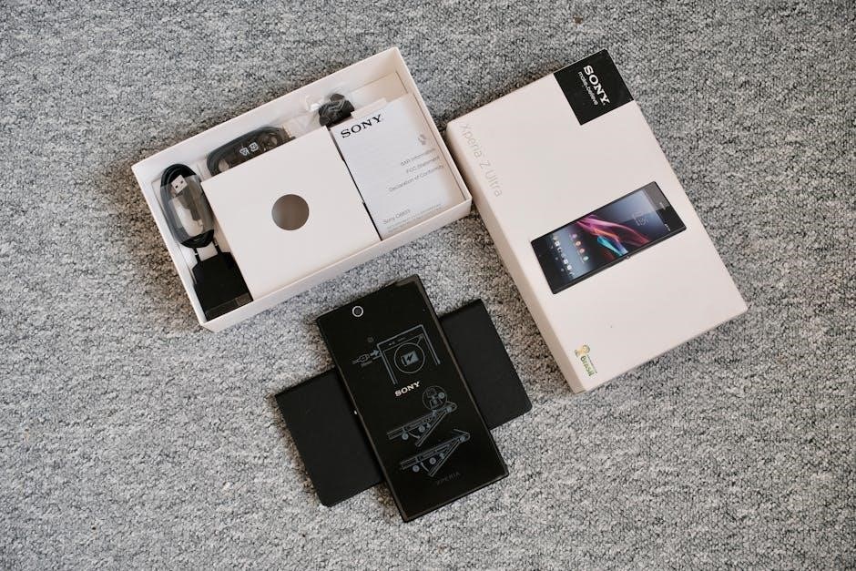
Upon receiving your Proselect thermostat, carefully inspect the package for any signs of damage during shipping. A damaged package may indicate potential issues with the unit itself. The standard package should include the thermostat unit, a mounting plate, screws and wall anchors for installation, and this user manual.
Some models may also include wire labels for easier identification during installation, and potentially, a small screwdriver. Do not discard the packaging until you’ve confirmed all components are present and the thermostat is functioning correctly.
Visually inspect the thermostat for any physical defects, such as cracks or loose parts. If any damage is detected, or if any components are missing, immediately contact Proselect customer support for assistance. Retain all original packaging materials as proof of purchase and for potential return or warranty claims. A thorough initial inspection ensures a smooth setup.

Installation & Wiring
Proceed with caution! This section details the installation process and wiring connections for your Proselect thermostat, ensuring safe and correct operation of your HVAC system.
Safety Precautions Before Installation
Crucially, disconnect power to your HVAC system at the breaker box before beginning any installation work. Failure to do so presents a serious risk of electrical shock, potentially causing severe injury or even fatality. Verify the power is off using a non-contact voltage tester at the thermostat wires.
Always consult a qualified HVAC technician if you are uncomfortable or unfamiliar with electrical wiring. Incorrect wiring can damage your thermostat, HVAC system, or create a fire hazard. Read all instructions thoroughly before starting.
Wear appropriate safety gear, including insulated gloves and eye protection. Keep the work area clean and free of obstructions. Do not install the thermostat in a location exposed to direct sunlight, extreme temperatures, or moisture. Ensure proper grounding to prevent electrical interference. Label all wires before disconnecting them from the old thermostat to facilitate accurate reconnection.
Wiring Diagrams for Common HVAC Systems
Understanding your HVAC system’s wiring is paramount for a successful Proselect thermostat installation. This section provides diagrams for frequently encountered configurations, but always verify compatibility with your specific system. Incorrect wiring can lead to malfunction or damage.
Refer to the detailed diagrams included below for single-stage, multi-stage, and heat pump systems. Each diagram clearly illustrates the corresponding terminal connections on both the thermostat and the HVAC control board. Pay close attention to wire colors, as they often indicate specific functions (e.g., R for power, W for heat, Y for cooling).
If your system deviates from these common setups, or if you encounter unfamiliar wiring, consult a qualified HVAC professional. Do not attempt to proceed without a clear understanding of the wiring configuration. Double-check all connections before restoring power to the system.
Wiring for Single-Stage Heating & Cooling
For systems with basic heating and cooling, the wiring is typically straightforward. Connect the ‘R’ wire (24VAC power) to the Rh terminal on the Proselect thermostat. The ‘W’ wire, controlling the heating system, connects to the W1 terminal. Similarly, the ‘Y’ wire, activating cooling, connects to the Y1 terminal.
The ‘G’ wire, responsible for fan operation, connects to the G terminal. A common wire, ‘C’, is highly recommended for stable power and consistent operation; connect it to the C terminal. Without a C-wire, some thermostat features may be limited or unreliable.
Ensure all wires are securely fastened to their respective terminals. Loose connections can cause intermittent operation or system failure. Double-check the wiring against the diagram before proceeding. If unsure, consult a qualified HVAC technician for assistance. Proper wiring is crucial for optimal performance.
Wiring for Multi-Stage Heating & Cooling
Multi-stage systems require careful wiring to utilize their efficiency benefits. Beyond the standard R, W, Y, G, and C wires, you’ll encounter additional wires for each stage. Connect the first-stage heating wire (W1) to the W1 terminal, and the second-stage heating wire (W2) to the W2 terminal on the Proselect thermostat.
Similarly, connect the first-stage cooling wire (Y1) to Y1, and the second-stage cooling wire (Y2) to Y2. Proper identification of these wires is critical; miswiring can lead to incorrect operation. Consult your HVAC system’s wiring diagram to confirm wire functions.
Ensure secure connections at all terminals. A ‘C’ wire remains essential for powering the thermostat and enabling multi-stage functionality. If you are unfamiliar with multi-stage wiring, professional installation is strongly advised to prevent damage or malfunction.
Wiring for Heat Pump Systems
Heat pump wiring differs significantly from conventional systems. Typically, you’ll encounter wires labeled O/B, Y, G, R, and C. The O/B wire is crucial – it’s the reversing valve control. Determine if your system uses an ‘O’ (cooling energizes the valve) or ‘B’ (heating energizes the valve) configuration. Incorrect setting will result in reversed heating and cooling.
Connect the Y wire to the Y terminal for compressor control. The G wire controls the fan, connecting to the G terminal. The R wire provides power, connecting to the R terminal, and the C wire is essential for common power. Carefully consult your heat pump’s wiring diagram to identify the O/B wire correctly.
Some heat pumps utilize auxiliary heat (AUX). Connect the AUX wire to the designated AUX terminal on the Proselect thermostat. Professional installation is highly recommended for heat pump wiring due to its complexity.

Thermostat Operation & Features
Explore intuitive controls and powerful features designed for optimal comfort and energy savings. This section details navigating the interface, setting temperatures, and scheduling options.
Navigating the User Interface
The Proselect thermostat boasts a user-friendly interface designed for effortless control. The primary display showcases the current room temperature, setpoint temperature, and operating mode (Heat, Cool, Auto, Off). Utilize the up and down arrow buttons to adjust the desired temperature with precision.
A central ‘Mode’ button allows seamless switching between heating, cooling, and automatic operation. Pressing the ‘Menu’ button unlocks advanced settings, including scheduling, fan control, and system configuration. The touchscreen (on applicable models) responds to gentle touches for intuitive navigation.
Icons clearly indicate active functions, such as Wi-Fi connectivity, filter change reminders, and hold status. A dedicated ‘Fan’ button provides control over fan operation – Auto, On, or Circulate. Explore the menu options to personalize display settings, including backlight brightness and temperature units (Fahrenheit or Celsius). Familiarize yourself with these controls to maximize your comfort and energy efficiency.
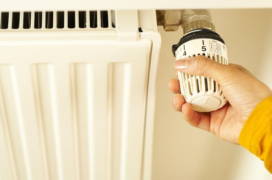
Setting the Temperature
Adjusting the temperature on your Proselect thermostat is straightforward. Use the prominently displayed up and down arrow buttons on the thermostat’s faceplate to increase or decrease the desired setpoint temperature. The current set temperature is clearly visible on the main display.
Each press of the arrow buttons typically adjusts the temperature by one degree, though this increment can be customized within the settings menu. Observe the thermostat’s response as you make adjustments; the system will initiate heating or cooling to reach the selected temperature.
For precise control, hold the arrow buttons for rapid temperature adjustments. The thermostat will display the target temperature as you modify it. Remember that the ‘Hold’ function, when activated, will maintain this set temperature indefinitely, overriding any programmed schedules. Experiment with different settings to find your optimal comfort level.
Programming Schedules
Efficiently manage your home’s climate with Proselect’s scheduling features. Access the programming mode through the main menu, typically indicated by a clock or calendar icon. You can create customized heating and cooling schedules tailored to your daily and weekly routines.
Proselect allows for multiple periods per day, enabling you to set different temperatures for wake, leave, return, and sleep times. Each period can be individually programmed with a specific temperature and start time. The thermostat supports seven-day schedules, or you can copy a schedule to multiple days for convenience.
Review your schedule carefully to ensure accuracy. Consider energy-saving settings for unoccupied periods. Utilize the ‘Hold’ functions to temporarily override the schedule when needed, maintaining comfort without disrupting your long-term programming.
Creating Daily & Weekly Schedules
To begin, access the ‘Schedule’ menu on your Proselect thermostat. You’ll typically navigate using the touchscreen or buttons. Select the day you wish to program – options include Monday through Sunday. Within each day, you can define up to four distinct periods: Wake, Leave, Return, and Sleep.
For each period, set the desired temperature and the exact start time. The thermostat will automatically transition between these temperatures based on your programmed schedule. To create a weekly schedule, program each day individually, or utilize the ‘Copy to’ function to replicate a schedule across multiple days.
Carefully review your programmed schedule to ensure it aligns with your lifestyle. Consider energy-saving temperatures during periods of inactivity. Save your schedule once completed, and the Proselect thermostat will automatically manage your home’s climate accordingly.
Using Hold Functions (Temporary & Permanent)
The ‘Hold’ function allows you to override your programmed schedule. A Temporary Hold maintains the current set temperature for a specified duration, after which the thermostat reverts to the scheduled program. To activate, select ‘Hold’ and input the desired hold time – options range from a few hours to 24 hours.
A Permanent Hold, conversely, disables the programmed schedule indefinitely, maintaining the selected temperature continuously. This is ideal for extended periods away or when a consistent temperature is preferred. To engage a Permanent Hold, select ‘Hold’ and confirm your choice when prompted.
To cancel a Hold and resume the programmed schedule, simply select ‘Resume’ or ‘Run Schedule’ within the thermostat’s menu. Remember to check which Hold function is active to ensure proper operation.
Advanced Features & Settings
Explore enhanced control! This section details Proselect’s advanced options – fan settings, filter reminders, display customization, Wi-Fi connectivity, and troubleshooting guidance.
Fan Control Options (Auto, On, Circulate)
Your Proselect thermostat offers three distinct fan control modes, allowing you to customize airflow for optimal comfort and air quality. Understanding these options is key to maximizing your system’s efficiency.
Auto Mode: In this setting, the fan operates only during heating or cooling cycles. This is the most energy-efficient option, as the fan isn’t running unnecessarily. It ensures air circulation only when temperature adjustments are being made.
On Mode: Selecting ‘On’ keeps the fan running continuously, regardless of whether the heating or cooling system is active. This provides consistent air circulation, which can be beneficial for even temperature distribution throughout your home and improved air filtration. However, it consumes more energy.
Circulate Mode: This intelligent mode runs the fan intermittently, even when heating or cooling isn’t required. It gently circulates air, preventing temperature stratification and maintaining a more consistent comfort level. The circulation cycle is typically around 15-20 minutes per hour, offering a balance between comfort and energy savings. To change fan settings, navigate to the ‘Fan’ option within the main menu on your thermostat’s display.
Filter Change Reminders
Maintaining a clean air filter is crucial for your HVAC system’s efficiency and your indoor air quality. Your Proselect thermostat includes a convenient filter change reminder feature to help you stay on schedule.
Setting the Reminder: Access the ‘Settings’ menu on your thermostat and locate the ‘Filter Reminder’ option. You can customize the reminder based on either time (e.g., every 30 days) or usage (e.g., after a specific number of heating/cooling hours). The recommended interval typically ranges from 1 to 3 months, depending on filter type and usage.
Reminder Notification: When the reminder is triggered, a notification will appear on the thermostat’s display. Some models may also send a notification to the connected mobile app, if Wi-Fi connectivity is enabled.
Resetting the Reminder: After replacing the air filter, remember to reset the reminder within the ‘Settings’ menu. This ensures accurate tracking for the next filter change. Ignoring filter change reminders can lead to reduced airflow, increased energy consumption, and potential system damage.
Backlight & Display Settings
Your Proselect thermostat offers customizable backlight and display settings to optimize visibility and energy conservation. Access these options through the ‘Settings’ menu on your device.
Backlight Control: You can adjust the backlight brightness to suit your preference and ambient lighting conditions. Options typically include ‘Auto’, ‘On’, and ‘Off’. ‘Auto’ dims the backlight after a period of inactivity, conserving energy. ‘On’ keeps the backlight continuously illuminated, while ‘Off’ disables it entirely.
Display Brightness: Fine-tune the overall display brightness to enhance readability. Lowering the brightness can also contribute to energy savings.
Display Timeout: Configure the display timeout setting to determine how long the screen remains active after the last button press. Shorter timeout durations minimize energy consumption. Some models offer a ‘Screen Saver’ option displaying a rotating clock or other information during inactivity.
Experiment with these settings to find the optimal balance between visibility and energy efficiency for your specific needs.
Wi-Fi Connectivity & Mobile App Control
Unlock remote control and advanced features by connecting your Proselect thermostat to your home Wi-Fi network. This enables control via the dedicated mobile app, available for both iOS and Android devices.
Connecting to Wi-Fi: Navigate to the ‘Network’ or ‘Wi-Fi’ settings on your thermostat. Select your network from the available list and enter your password. A successful connection will be indicated by a Wi-Fi icon on the display.
Mobile App Features: The mobile app mirrors the thermostat’s functionality, allowing you to adjust temperature, create schedules, and monitor energy usage remotely. You can also receive alerts for extreme temperatures or system malfunctions.
Account Creation: You’ll need to create a Proselect account to utilize the mobile app. Follow the in-app instructions to register and link your thermostat. Ensure your thermostat’s firmware is up-to-date for optimal app compatibility.
Enjoy the convenience and control of managing your home comfort from anywhere!
Troubleshooting Common Issues
Thermostat Not Powering On: Verify the wiring connections and ensure the power supply is active. Check the circuit breaker. If issues persist, consult a qualified HVAC technician.
No Heating or Cooling: Confirm the system is set to the correct mode (Heat, Cool, Auto). Inspect air filters for blockage. Ensure the thermostat is calling for heat or cool – check the set temperature.
Wi-Fi Connection Problems: Restart your router and thermostat. Double-check the Wi-Fi password entered in the thermostat settings. Ensure the thermostat is within range of your Wi-Fi signal.
Incorrect Temperature Readings: Calibrate the thermostat if necessary, following the instructions in the ‘Advanced Settings’ section. Avoid direct sunlight or drafts affecting the sensor.
App Connectivity Issues: Ensure the thermostat is online. Force close and reopen the mobile app. Verify your internet connection. Contact Proselect support if problems continue.
Technical Specifications
Model Number: PX-T1000 (Example – varies by specific model).
Power Supply: 24VAC, Common (C) wire required for optimal performance. Battery backup: 2 x AA Alkaline batteries (not included).
Temperature Range: 40°F to 90°F (4°C to 32°C) – Display Range: 32°F to 100°F (0°C to 38°C).
Accuracy: ±1°F (±0.5°C).
Connectivity: Wi-Fi 802.11 b/g/n (2.4 GHz). Mobile app compatible with iOS and Android.
Display: Backlit LCD with adjustable brightness.

Relay Capacity: Heating: 24VAC, 0.5A; Cooling: 24VAC, 0.5A; Fan: 24VAC, 0.5A.
Dimensions: 4.7” x 3.9” x 1.2” (119mm x 99mm x 30mm).
Operating Humidity: 10% to 90% non-condensing.

Certifications: UL Listed, FCC Compliant.
Warranty: 2-Year Limited Warranty.