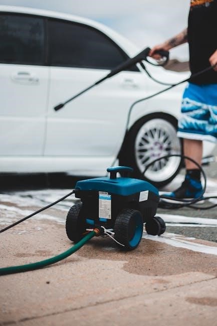
Troy-Bilt offers robust power washers, utilizing Briggs & Stratton engines, designed for diverse cleaning tasks around homes and properties.
These washers, often available at retailers like Lowes, Walmart, and Amazon, provide effective solutions for various outdoor cleaning needs.
What is a Troy-Bilt Power Washer?
Troy-Bilt power washers are gas-powered cleaning machines engineered to deliver high-pressure water streams for removing dirt, grime, and debris from surfaces. They are commonly equipped with Briggs & Stratton engines, known for their reliability and power, offering torque levels like 8.75 ft-lbs.
These washers come in various models, including those with 3000 PSI/2.7 GPM and 3300 PSI/2.4 GPM specifications, catering to different cleaning demands. Troy-Bilt washers often include multiple spray tips – 0°, 25°, 40° – and sometimes a second story nozzle kit for extended reach, enhancing versatility. They are designed for residential and light commercial use, providing a powerful cleaning solution for homeowners.
Benefits of Using a Troy-Bilt Power Washer
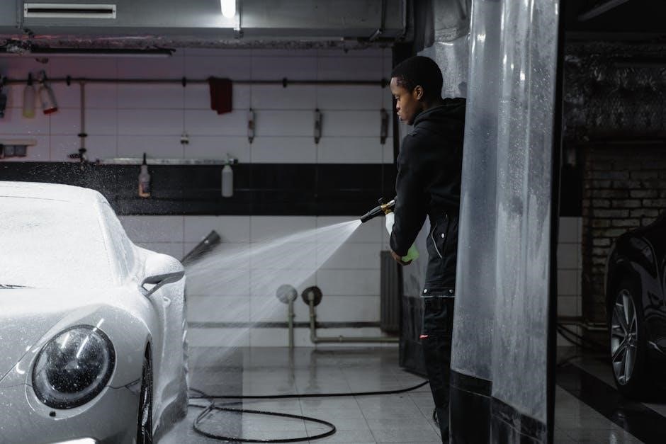
Troy-Bilt power washers offer significant time and effort savings compared to manual cleaning methods. Their high-pressure streams quickly remove stubborn dirt and grime from decks, siding, driveways, and vehicles. The inclusion of multiple nozzles – like 0°, 25°, and 40° – allows for adaptable cleaning, tackling various surfaces and soil levels.
Models with features like the second story nozzle kit extend cleaning reach, while the Briggs & Stratton engines provide reliable power. Furthermore, adhering to PWMA standards (PW 101-2010) ensures performance consistency and user safety, making them a valuable tool for maintaining property appearance.

Understanding Troy-Bilt Power Washer Models
Troy-Bilt offers diverse models, including 3000 PSI 2.7 GPM and 3300 PSI 2.4 GPM options, powered by robust engines for varied cleaning demands.
3000 PSI 2.7 GPM Models
Troy-Bilt’s 3000 PSI 2.7 GPM models, frequently found at Lowes, represent a strong balance of power and water volume for many homeowner tasks. These pressure washers are equipped with a Briggs & Stratton Professional Series engine, delivering 8.75 ft-lbs of gross torque.
The ReadyStart system and Fresh Start fuel cap enhance engine reliability and performance. Included are multiple spray tips – 0°, 25°, and 40° – alongside a second story nozzle for extended reach. The exclusive Troy-Bilt XP spray gun offers a comfortable, ergonomic design, and the fold-down handle simplifies storage.
3300 PSI 2.4 GPM Models
Troy-Bilt offers 3300 PSI 2.4 GPM gas pressure washers, available at retailers like Walmart, powered by a 195cc CT200 engine and an axial cam pump. This combination delivers substantial cleaning power for tougher jobs around the property.
These models are designed for effective grime removal, boasting a maximum pressure of 3300 PSI and a water flow rate of 2.4 GPM. The robust engine ensures reliable performance, while the axial cam pump contributes to efficient operation. These washers provide a powerful cleaning solution for various outdoor surfaces.
Model Variations and Key Differences
Troy-Bilt power washer models primarily differ in PSI (pounds per square inch) and GPM (gallons per minute), impacting cleaning power and efficiency. The 3000 PSI 2.7 GPM models, found at Lowes, prioritize a balance between pressure and water volume, suitable for general cleaning.
Conversely, the 3300 PSI 2.4 GPM versions, available at Walmart, offer higher pressure for tackling stubborn dirt, though with a slightly reduced flow rate. Engine specifications and included nozzle kits also vary, influencing overall usability and application.
Key Components of a Troy-Bilt Power Washer
Troy-Bilt power washers feature Briggs & Stratton engines, axial cam pumps, and specialized spray guns with multiple nozzles for versatile cleaning applications.
Engine Specifications (Briggs & Stratton)
Troy-Bilt power washers commonly utilize Briggs & Stratton engines, renowned for their reliability and performance. Many models feature the Professional Series OHV engines, delivering substantial gross torque – for example, 8.75 ft-lbs.
These engines incorporate features like the ReadyStart system, simplifying the starting process, and a Fresh Start fuel cap, promoting cooler operation and extended engine life. The 195cc CT200 engine is also frequently employed, providing ample power for demanding cleaning tasks.
Proper engine maintenance, as detailed in the owner’s manual, is crucial for optimal performance and longevity.
Pump Type: Axial Cam Pumps
Troy-Bilt power washers predominantly employ axial cam pumps, a popular choice for gas-powered pressure washing systems. These pumps are known for their durability and ability to generate high pressure, effectively tackling tough cleaning jobs.
The axial cam design converts the rotational motion of the engine into pulsating high-pressure water flow. Models like the 3300 PSI version utilize this pump type, delivering 2.4 GPM for efficient cleaning.
Regular pump maintenance, outlined in the user manual, ensures consistent performance and extends the pump’s lifespan.
Spray Gun and Nozzle System
Troy-Bilt power washers feature a spray gun designed for comfortable operation, often incorporating a soft-grip for extended use. The included nozzle system is a key component, offering versatility for different cleaning applications.
Many models, like the 3000 PSI version at Lowes, come with multiple quick-connect tips – 0°, 25°, and 40° – alongside a soap nozzle and a second story nozzle kit.
The manual details proper nozzle selection based on cleaning surface and desired intensity, ensuring optimal results and preventing damage.
Using Your Troy-Bilt Power Washer
Troy-Bilt power washers require careful setup, including water connection and engine starting, as detailed in the owner’s manual for safe operation.
Safety Precautions
Prior to operation, thoroughly review the Troy-Bilt power washer manual for crucial safety guidelines; Always wear safety glasses or goggles to protect your eyes from debris. Closed-toe shoes are essential, and consider hearing protection due to engine noise.
Never point the spray wand at yourself or others. Maintain a safe distance from electrical sources, and avoid using the power washer on electrical components. Ensure a stable footing while operating, and be mindful of the recoil force from the spray wand.
Disconnect the power washer from the water supply and engine when not in use or during maintenance. Properly store the unit in a dry, secure location, out of reach of children.
Connecting Water Supply
Before starting, ensure the Troy-Bilt power washer is switched off. Attach a standard garden hose to the water inlet on the pump. It’s recommended to use a 25-foot hose for optimal reach and pressure. Check for any kinks or obstructions within the hose.
Fully open the water supply valve to provide adequate water flow to the pump. Low water pressure can damage the pump, so verify sufficient supply.
Purge the hose by running the water briefly before connecting it to the washer, removing any trapped air or debris. Always refer to your specific model’s manual for detailed instructions regarding water supply connection.
Starting the Engine
Ensure the power washer is on a level surface and the water supply is connected and fully open. Check the oil level, adding oil if necessary, according to your Troy-Bilt model’s specifications. Confirm the fuel tank contains fresh gasoline.
Turn the fuel valve to the ‘ON’ position. If equipped, set the choke to the ‘START’ position. Then, firmly pull the starter rope until the engine starts. Gradually return the choke to the ‘RUN’ position as the engine warms up.
Always consult your owner’s manual for specific starting procedures related to your model.

Nozzle Selection and Application
Troy-Bilt power washers include multiple nozzles – 0°, 25°, 40° – and soap/jet nozzles, each designed for specific cleaning applications and surface types.
0-Degree Nozzle: For Intense Cleaning
The 0-degree nozzle delivers a highly concentrated, powerful spray stream, making it ideal for tackling stubborn dirt, grime, and stains on durable surfaces.
However, caution is crucial! This intense pressure can easily damage softer materials like wood, painted surfaces, or vehicle finishes.
Always test in an inconspicuous area first and maintain a safe distance.
Use it for concrete, heavily soiled brick, or metal, but avoid delicate surfaces to prevent etching or damage.
Proper technique and awareness are key when utilizing this potent cleaning tool.
25-Degree Nozzle: All-Purpose Cleaning
The 25-degree nozzle is your go-to for a wide range of cleaning tasks, offering a versatile balance between power and surface protection.
It’s effective on most exterior surfaces, including siding, decks, patios, and driveways, removing dirt, mildew, and algae without causing significant damage.
This nozzle is a great starting point for many cleaning projects, providing a broader spray pattern than the 0-degree option.
It’s suitable for general washing and rinsing, making it a frequently used attachment for Troy-Bilt power washers.
40-Degree Nozzle: Wider Coverage
The 40-degree nozzle delivers a wider spray pattern, making it ideal for quickly cleaning large, relatively flat surfaces.
It’s perfect for washing fences, large patio areas, or vehicle exteriors, covering more ground with each pass.
Due to its lower pressure, it’s less likely to damage delicate surfaces compared to narrower-angle nozzles.
This nozzle excels at rinsing away loose debris and applying cleaning solutions over expansive areas efficiently.
It’s a valuable tool for tasks where broad coverage and gentle cleaning are prioritized with your Troy-Bilt power washer.
Soap Nozzle: Applying Detergents
The soap nozzle, often included in Troy-Bilt kits like those at Lowes, is specifically designed for applying detergents and cleaning solutions.
It creates a low-pressure, high-volume spray that effectively mixes soap with water, maximizing cleaning power.
This nozzle typically features a wider spray pattern to ensure even distribution of the cleaning agent across the surface.
Always use detergents formulated for pressure washers to avoid damaging the pump or the surface being cleaned.
Proper use of the soap nozzle significantly enhances the effectiveness of your Troy-Bilt power washer for tackling stubborn grime.
Second Story Nozzle Kit: Reaching Higher Areas
Troy-Bilt often includes a second story nozzle kit, as seen at Lowes, to extend the reach of your power washer for cleaning elevated surfaces.
This kit typically consists of wand extensions and specialized nozzles designed for longer-distance spraying.
These nozzles deliver a focused stream, allowing you to effectively clean siding, gutters, and other hard-to-reach areas.
Always exercise caution when using extensions, ensuring a stable footing and maintaining awareness of your surroundings.
Proper use of the kit maximizes the versatility of your Troy-Bilt power washer, simplifying challenging cleaning tasks.
Maintenance and Troubleshooting
Regular upkeep, including winterizing, ensures longevity; common issues like engine starting can often be resolved with simple checks and adjustments.
Regular Maintenance Schedule
To maximize the lifespan and performance of your Troy-Bilt power washer, a consistent maintenance schedule is crucial. After each use, thoroughly flush the system with clean water to remove any residual detergents or debris. Regularly inspect hoses and connections for leaks or damage, replacing them as needed.
Annually, change the engine oil according to the Briggs & Stratton engine manual’s recommendations. Clean or replace the air filter to ensure optimal engine performance. Inspect the spray gun and nozzles for clogs, cleaning or replacing them to maintain consistent spray patterns. Proper storage during off-season, especially winterizing, is also vital.
Winterizing Your Power Washer
Proper winterization prevents damage from freezing temperatures. First, disconnect the water supply and drain all remaining water from the pump, hoses, and tank. Utilize a pump saver kit, adding antifreeze to protect internal components. Change the engine oil, as cold temperatures can thicken existing oil, hindering startup.
Remove the spark plug and pour a small amount of engine oil into the cylinder, then pull the starter cord to distribute it. Store the power washer in a dry, protected area, covering it to prevent dust accumulation. Following these steps ensures a trouble-free start next spring.
Common Problems and Solutions
If the engine fails to start, check the fuel level, spark plug, and air filter. A clogged nozzle can reduce pressure; soak it in vinegar or use a nozzle cleaning tool. Low pressure may also indicate a faulty pump or a kinked water hose – inspect both carefully.
For overheating, ensure adequate ventilation and check the oil level. If the unit vibrates excessively, tighten any loose bolts. Always consult the Troy-Bilt manual for specific troubleshooting steps and safety precautions before attempting repairs.

Finding Troy-Bilt Power Washer Manuals
Access manuals easily through the official Troy-Bilt website, major retailers like Lowes and Walmart, or through authorized dealers such as Bignells Power Sports.
Official Troy-Bilt Website
The official Troy-Bilt website serves as the primary resource for locating comprehensive power washer manuals. Users can typically find manuals by entering the model number of their specific pressure washer into the search bar on the site.
This ensures they access the correct documentation tailored to their machine. The website often provides downloadable PDF versions of the manuals, offering convenient access for viewing and printing.
Beyond manuals, the Troy-Bilt website also features helpful resources like parts diagrams, troubleshooting guides, and frequently asked questions, further assisting owners in maintaining and operating their power washers effectively.
Retailer Websites (Lowes, Walmart, Amazon)
Major retailers like Lowes, Walmart, and Amazon frequently offer digital copies of Troy-Bilt power washer manuals directly on their product pages. These are often found within the “Support” or “Documents” section associated with the specific model.
Customers who purchased the washer through these retailers can conveniently access the manual without needing to navigate to the official Troy-Bilt website.
However, availability can vary, so it’s always prudent to cross-reference with the manufacturer’s site to ensure you have the most up-to-date and complete version of the manual.
Dealer Networks (Bignells Power Sports)
Local Troy-Bilt dealers, such as Bignells Power Sports in Westfield, Wisconsin, are valuable resources for obtaining physical copies of power washer manuals. These dealerships often stock manuals for the models they sell and can assist customers who prefer a hard copy.
Furthermore, dealer networks frequently have knowledgeable staff who can guide you through the manual’s contents or answer specific questions about your Troy-Bilt power washer.
Visiting a dealer provides a personalized experience and ensures you receive accurate information tailored to your particular model.
Pressure Washer Ratings and Standards
Troy-Bilt pressure washers adhere to PWMA standard PW 101-2010, ensuring consistent performance ratings of PSI and GPM for reliable cleaning.
PWMA Standard PW 101-2010
Troy-Bilt, like other reputable pressure washer manufacturers, utilizes the Pressure Washer Manufacturers Association (PWMA) standard PW 101-2010 for testing and rating performance. This standard ensures transparency and consistency in how pressure washers are evaluated, allowing consumers to make informed purchasing decisions.
PW 101-2010 defines specific testing procedures to determine both PSI (pounds per square inch) – measuring the water pressure – and GPM (gallons per minute) – indicating the water flow rate. Adherence to this standard guarantees that the stated PSI and GPM values accurately reflect the washer’s cleaning capability, providing a reliable benchmark for comparison across different brands and models.
Understanding PSI and GPM
When selecting a Troy-Bilt power washer, understanding PSI (pounds per square inch) and GPM (gallons per minute) is crucial. PSI dictates the force of the water stream, impacting its ability to remove stubborn dirt and grime; higher PSI means more powerful cleaning.
However, GPM determines how quickly an area can be cleaned. A higher GPM washes away debris faster, increasing efficiency. Troy-Bilt models range from 3000 PSI/2.7 GPM to 3300 PSI/2.4 GPM, offering options for various tasks – from delicate cleaning to heavy-duty applications.

Purchasing a Troy-Bilt Power Washer
Troy-Bilt power washers are readily available at major retailers like Lowes, Walmart, and Amazon, with prices varying based on PSI and GPM.

Where to Buy
Troy-Bilt power washers boast widespread availability, ensuring convenient access for consumers nationwide. Major retailers consistently stock a variety of models, including Lowes, Walmart, and Amazon. These outlets frequently feature both online and in-store purchasing options, catering to diverse shopping preferences.
For those seeking specialized service and a broader selection, authorized Troy-Bilt dealers, such as Bignells Power Sports in Westfield, Wisconsin, provide expert guidance and can fulfill orders for specific models. Checking retailer websites allows for price comparisons and availability checks before visiting a store, streamlining the purchasing process.
Price Ranges
Troy-Bilt power washer pricing varies considerably based on power, features, and retailer. Generally, consumers can expect to find models ranging from around $100 to upwards of $450. Entry-level units, suitable for lighter tasks, typically fall within the $100-$300 bracket.
More powerful models, featuring higher PSI and GPM ratings, along with enhanced features like axial cam pumps and multiple nozzles, often range from $300 to $450 or more. Amazon and other online retailers frequently offer discounts and promotions, potentially lowering these price points. Always compare prices across different vendors.
Warranty Information
Troy-Bilt power washer warranties typically cover defects in materials and workmanship for a specified period. Engine warranties, often provided by Briggs & Stratton, are usually separate from the power washer unit’s warranty. Standard warranties generally range from one to three years on the power washer itself, and potentially longer on the engine.
It’s crucial to register your product upon purchase to activate the warranty. Review the specific warranty documentation included with your model for complete details, including what is covered and any limitations. Proof of purchase is required for all warranty claims.