gardepro a3s trail camera manual

GardePro A3S Trail Camera Manual: A Comprehensive Guide

This manual provides detailed instructions for setting up, operating, and troubleshooting the GardePro A3S trail camera, ensuring optimal performance and user satisfaction․

The GardePro A3S is a cutting-edge, non-cellular trail camera designed for wildlife observation and security purposes․ This new generation digital scouting camera boasts impressive features, including high-resolution image and video capture․

It’s remarkably user-friendly, requiring 8 AA batteries (Alkaline or Lithium) for operation․ The A3S is waterproof, ensuring reliable performance in various weather conditions, and comes equipped with a mounting strap for versatile placement․

What’s in the Box?

Upon opening your GardePro A3S package, you’ll find several essential components to get you started․ The box includes one A3S camera unit, a durable mounting strap for secure installation, and a comprehensive instruction manual to guide you through setup and operation․

Additionally, a USB cord is provided for data transfer and potential firmware updates․ Please note that a microSD card and batteries are not included and must be purchased separately․
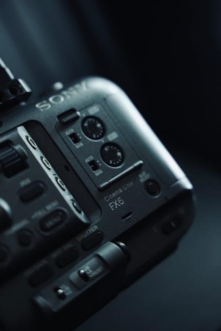
Camera Components

The GardePro A3S features a robust, weather-resistant casing designed for outdoor use․ Key components include a high-resolution lens for capturing clear images and videos, an integrated motion sensor for reliable detection, and a user-friendly control panel with buttons for menu navigation․

A built-in LCD screen displays settings and captured media, while a microSD card slot accommodates storage․ The camera also has a USB port for connectivity․

Included Accessories

Your GardePro A3S package includes the camera itself, a durable mounting strap for secure attachment to trees or posts, and a comprehensive instruction manual to guide you through setup and operation․ A USB cord is provided for data transfer and potential firmware updates․

Please note that batteries and a microSD card are not included and must be purchased separately for full functionality․

Initial Setup

Before deploying your GardePro A3S, proper initial setup is crucial․ This involves installing the required batteries – either 8 Alkaline or Lithium AA batteries – to power the device․ Subsequently, insert a compatible microSD card (not included) to store captured images and videos․

Ensure the card is correctly seated for optimal performance․

Installing Batteries

To install batteries, locate the battery compartment on the GardePro A3S․ Open the compartment and insert eight AA batteries, ensuring correct polarity as indicated inside․ Alkaline or Lithium batteries are supported for reliable performance․ Close the compartment securely to ensure a waterproof seal and proper camera operation․

Inserting a MicroSD Card

Insert a MicroSD card into the designated slot on the GardePro A3S․ Ensure the card is compatible and properly formatted (FAT32)․ Gently push the card in until it clicks into place․ The camera requires a MicroSD card to store captured images and videos; without one, it will not function correctly․

Understanding the Camera Interface

The GardePro A3S features a user-friendly interface with several buttons for navigation and control․ Familiarize yourself with the MENU, UP, DOWN, OK, and SHOT buttons․ A clear display screen showcases camera settings, battery life, and captured image previews․ Understanding these elements is crucial for efficient operation․

Button Functions

The MENU button accesses the camera’s settings․ UP/DOWN buttons navigate through menu options and adjust settings values․ OK button confirms selections․ The SHOT button initiates test photos or videos․ These buttons allow full control over the A3S, enabling customization of image capture and camera behavior for specific scouting needs․

Display Icons and Indicators

The LCD screen displays vital camera information․ Battery level is indicated by an icon․ SD card status shows if a card is inserted and its remaining capacity․ Signal strength (if applicable) is displayed․ Capture mode (photo/video) is clearly shown, alongside time, date, and temperature readings for comprehensive monitoring․

Navigating the Menu

The GardePro A3S features an intuitive menu system․ Pressing the MENU key grants access to all settings․ Use the UP/DOWN buttons to scroll through options․ Confirm selections with the OK/Shoot button․ Exit the menu at any time by pressing MENU again, ensuring easy and efficient camera configuration․

Accessing the Main Menu

To enter the main menu on your GardePro A3S, ensure the camera is in SET mode․ Simply press the MENU key․ The display will then present a list of configurable options․ Navigating this menu allows full customization of camera settings, tailoring it to your specific surveillance needs․

Menu Options Overview

The main menu of the GardePro A3S offers diverse settings․ These include image and video resolution adjustments, trigger sensitivity control, time lapse and interval recording configurations, and options for date/time settings․ Users can also manage storage and review camera information within this intuitive interface․

Camera Settings Configuration

Configure your GardePro A3S for optimal results through its settings․ Adjust image resolution for clarity, selecting from available options․ Similarly, customize video resolution to balance quality and storage․ Explore settings for date/time, volume, and other preferences to tailor the camera to your specific monitoring needs․

Image Resolution Settings

The GardePro A3S offers various image resolution options, impacting file size and detail․ Higher resolutions (e․g․, 20MP) capture more detail but require more storage space on your microSD card․ Lower resolutions (e․g․, 8MP) conserve space, suitable for general surveillance․ Select the resolution that best balances image quality and storage capacity․

Video Resolution Settings

The GardePro A3S allows adjustment of video resolution, influencing file size and clarity․ Options typically include 1080p, 720p, and VGA․ Higher resolutions (1080p) provide sharper video but consume more storage․ Lower resolutions (VGA) are suitable for shorter clips or limited storage․ Adjust settings based on desired video quality and microSD card capacity;

Trigger Settings

Trigger settings on the GardePro A3S control how the camera activates․ Detection Sensitivity adjusts the range at which motion is detected – higher for greater range, lower to reduce false triggers․ Trigger Speed determines how quickly the camera captures an image or video after motion is sensed, impacting responsiveness․

Detection Sensitivity Adjustment

Adjusting detection sensitivity on your GardePro A3S is crucial for optimal performance․ Higher sensitivity increases the detection range, potentially capturing more activity, but also increasing false triggers from wind or small animals; Lower sensitivity reduces false triggers but may miss distant movement․ Experiment to find the ideal setting for your location․

Trigger Speed Configuration

The GardePro A3S boasts a swift trigger speed, vital for capturing fast-moving wildlife․ While specific settings aren’t detailed, optimizing this feature involves balancing responsiveness with battery life․ Faster trigger speeds consume more power․ Consider the typical animal activity in your area when configuring this setting for best results․

Time Lapse and Interval Settings

The GardePro A3S allows for automated time-lapse photography and interval recording․ These features capture images at pre-defined intervals, ideal for monitoring plant growth or documenting wildlife patterns over extended periods; Configuration involves setting the interval duration and start/stop times within the camera’s menu system․

Setting Up Time Lapse Photography

To initiate time-lapse, navigate to the relevant menu option․ Specify the interval – the time between each captured image – ranging from seconds to hours․ Define a start time and an end time to control the duration of the time-lapse sequence․ Ensure sufficient microSD card space for storing the resulting images․

Configuring Interval Recording

Interval recording allows capturing footage at set time intervals, conserving storage; Access the menu and select the interval recording function․ Define the recording duration and the interval between each recording segment, typically in minutes or hours․ Confirm settings and activate to begin scheduled video capture․

Testing the Camera

Thorough testing is crucial before deployment․ Initiate a test recording by walking in front of the camera to trigger the motion sensor․ Afterwards, review the captured images and videos on a computer․ Verify clarity, trigger speed, and overall image/video quality․ Adjust settings as needed to optimize performance for your specific environment․

Performing a Test Recording

To conduct a test, power on the GardePro A3S and ensure a MicroSD card is installed․ Walk across the camera’s field of view, simulating wildlife movement․ Return to the camera and navigate the menu to review the recorded image or video․ This confirms the trigger and recording functions are operating correctly․

Checking Image and Video Quality

After a test recording, carefully review the captured images and videos on the camera’s display or a computer․ Assess clarity, brightness, and overall detail․ Ensure the image resolution and video settings are configured to your preference․ Adjust settings if necessary to optimize image and video quality for your specific environment․

Mounting the Camera

Securely mounting the GardePro A3S is crucial for optimal performance․ Select locations with clear views, avoiding direct sunlight or obstructions․ Utilize the provided mounting strap, ensuring a firm and stable attachment to a tree or post․ Regularly check the mounting to prevent shifting due to weather or wildlife․

Optimal Mounting Locations

Ideal locations for the GardePro A3S include game trails, feeding areas, and near water sources․ Choose spots offering a clear field of view, approximately 5-10 feet above the ground․ Avoid dense foliage or areas with excessive movement from wind․ North or south-facing positions minimize direct sunlight interference․

Using the Mounting Strap

Securely attach the GardePro A3S using the provided strap, threading it through the mounting slots on the camera’s back․ Wrap the strap tightly around a tree or post, ensuring a firm and stable hold․ Regularly check the strap’s tension, especially after weather changes, to prevent camera movement or fall․

Firmware Updates

Regular firmware updates enhance the GardePro A3S’s performance and add new features․ Download the latest version from the official GardePro Download Center․ Copy the firmware file to a MicroSD card, then follow the on-screen instructions within the camera’s menu to initiate the upgrade process․

Downloading the Latest Firmware

Access the official GardePro Download Center to locate the most recent firmware for your A3S camera․ Ensure you select the correct firmware version specifically designed for this model․ The firmware is typically available as a PDF or downloadable file, ready for transfer to a MicroSD card for easy updating․

Instructions for Firmware Upgrading

First, copy the downloaded firmware file onto the root directory of your MicroSD card․ Insert the card into the A3S camera, ensuring it’s powered off․ Then, follow the on-screen prompts within the camera’s menu to initiate the upgrade process․ Do not interrupt power during the update!

Troubleshooting Common Issues

If the camera fails to power on, verify battery polarity and charge levels․ For poor image quality, check lens cleanliness and ensure the correct resolution settings are selected․ Confirm a compatible MicroSD card is installed correctly․ Refer to the manual for detailed solutions and contact support if issues persist․

Camera Not Powering On

Ensure you’re using fresh, high-quality Alkaline or Lithium AA batteries, correctly installed with proper polarity․ A faulty battery connection is a common cause․ Verify the batteries haven’t corroded․ If the issue continues, test with a different set of batteries to isolate the problem․ Consult the manual’s diagrams․

Poor Image Quality

Check the lens for obstructions like dirt, debris, or condensation․ Clean it gently with a soft cloth․ Adjust image resolution settings within the menu for higher quality․ Ensure sufficient lighting; low light impacts clarity․ Verify the MicroSD card isn’t full or damaged, as this can cause image corruption․ Review trigger settings․

Understanding the Camera’s Waterproof Rating

The GardePro A3S is designed for weather resistance, but isn’t submersible․ Ensure all battery and SD card compartments are securely closed․ Avoid prolonged exposure to direct water streams․ Inspect seals regularly for damage․ Proper mounting, shielded from rain, enhances longevity․ While waterproof, careful practices maximize protection against the elements․

Water Resistance Capabilities

The A3S boasts robust weatherproofing, protecting against rain, snow, and humidity․ However, it’s not fully waterproof; avoid submersion․ The camera’s casing prevents moisture ingress during typical outdoor conditions․ Sealed battery and SD card compartments contribute to its resistance․ Regularly check for seal integrity to maintain optimal protection against the elements․

Proper Waterproofing Practices

To maximize water resistance, ensure the camera’s battery and SD card compartments are securely closed․ Avoid direct exposure to high-pressure water sources like power washers․ Periodically inspect rubber seals for damage or debris․ Consider using a protective housing for extreme weather․ Mount the camera under cover when possible, shielding it from direct rainfall․

Downloading the Instruction Manual

Access the official GardePro Download Center online to obtain the latest A3S trail camera instruction manual․ Available in multiple languages – English, French, German, Italian, and Spanish – the PDF version, GardePro_A3S_Instruction_Manual_V1, offers comprehensive guidance; Ensure you download the correct version for your region and camera model for optimal understanding․

Accessing the Official GardePro Download Center

To find the GardePro Download Center, simply search online for “GardePro Download Center” using your preferred search engine․ This will direct you to the official website where you can locate and download instruction manuals for all GardePro products, including the A3S trail camera․ Ensure a stable internet connection for a smooth download process․

Available Language Options for the Manual

The GardePro A3S instruction manual is thoughtfully provided in multiple languages to cater to a global user base․ Currently, available options include English (EN), French (FR), German (DE), Italian (IT), and Spanish (ES)․ Download the version that best suits your language preference for easy understanding and optimal camera operation․

Frequently Asked Questions (FAQ)

Regarding battery life, expect varying performance based on usage and battery type; lithium batteries generally offer longer life․ MicroSD card compatibility requires cards up to 32GB; ensure proper formatting for optimal performance․ For further assistance, consult the complete manual or contact GardePro customer support․

Battery Life Expectancy

Battery life on the GardePro A3S varies significantly․ Using alkaline batteries, anticipate around 6 months in standby mode, while lithium batteries can extend this to a year․ Frequent triggering and video recording will reduce operational time․ Regularly check battery levels for consistent performance․

MicroSD Card Compatibility

The GardePro A3S supports MicroSD cards up to 32GB․ Ensure the card is formatted to FAT32 for optimal compatibility․ Using higher capacity cards may result in functionality issues․ Regularly format the card within the camera to maintain reliable performance and prevent data corruption during image and video capture․

Warranty Information

GardePro offers warranty coverage for the A3S trail camera against manufacturing defects․ This coverage typically lasts for one year from the date of original purchase․ To initiate a warranty claim, contact GardePro customer support with proof of purchase․ Warranty does not cover damage from misuse or acts of nature․

GardePro Warranty Coverage

GardePro’s warranty covers defects in materials and workmanship under normal use for one year․ This excludes damage resulting from improper installation, accidents, abuse, or unauthorized modifications․ The warranty provides repair or replacement at GardePro’s discretion․ Proof of purchase is required for all claims․

Contacting Customer Support

GardePro offers customer support through their official website, providing access to FAQs and troubleshooting resources․ For direct assistance, users can reach out via email or explore the GardePro Facebook Group for community support․ Prompt responses and helpful solutions are prioritized to ensure customer satisfaction․

cobra microtalk walkie talkie manual

Cobra MicroTalk Walkie Talkie Manual: A Comprehensive Guide

This manual provides detailed instructions for Cobra MicroTalk two-way radios, covering features like scanning, privacy codes, and power-saving standby modes for optimal use.

Welcome to the world of reliable communication with your Cobra MicroTalk two-way radio! These radios are designed for convenient, short-range communication, offering up to a 3-mile range (depending on the model and terrain). They feature 8 channels for diverse user needs and incorporate useful functions like automatic channel scanning and privacy codes (CTCSS/DCS).

This guide will walk you through the operation of your MicroTalk radio, from powering it on and adjusting the volume to utilizing advanced features like the Roger Beep and message recording.

Understanding Key Features

Cobra MicroTalk radios boast several key features enhancing usability. The MODE/POWER button controls power and channel selection. An ON/OFF volume control adjusts audio levels, while a LOCK function prevents accidental button presses. The Push-to-Talk (PTT) initiates transmission, signaled by the Roger Beep.

Additional features include automatic channel scanning, Tri-Watch mode, and privacy codes (CTCSS/DCS) for secure communication. Message recording/playback adds convenience, and the MEM/ESC button provides versatile functionality.

Range and Channel Capacity

Cobra MicroTalk radios typically offer a communication range of up to 3 kilometers (2 miles), and some models reach 5 kilometers (3 miles). This range is dependent on terrain and conditions. These radios commonly feature 8 channels, allowing users to select different frequencies for communication.

Utilizing these channels, combined with CTCSS/DCS codes, minimizes interference and enhances privacy during conversations. The automatic channel scan efficiently searches for active channels.

Typical Range of Cobra MicroTalk Radios

The typical range for Cobra MicroTalk radios is approximately 3 kilometers (2 miles), though certain models can extend this to 5 kilometers (3 miles). However, actual range is significantly impacted by environmental factors. Obstacles like buildings, trees, and terrain can reduce effective communication distance.

Clear, open areas provide the best performance, maximizing the potential range of your MicroTalk radio.

Available Channels (e.g., 8 Channels)

Cobra MicroTalk radios commonly feature 8 channels, allowing users to select different frequencies for communication. Utilizing multiple channels helps minimize interference from other radio users in the vicinity. Scanning through available channels is recommended to find the clearest signal.

Each channel represents a specific frequency, and selecting the optimal one enhances communication quality and reduces static or disruptions.

Powering On and Off

To activate your Cobra MicroTalk radio, press and hold the MODE/POWER button until audible tones confirm it’s on. The radio enters listening mode, ready for transmissions. To conserve battery life, the radio automatically enters standby mode after 12 seconds of inactivity—no button presses.

Simply pressing the MODE/POWER button again will reactivate it from standby. Remember to turn the radio off while charging for optimal battery health.

Turning the Radio On: MODE/POWER Button

Initiating power-up is simple: press and firmly hold the MODE/POWER button. Continue holding until you distinctly hear a series of audible tones. These tones signify the radio is successfully powered on and operational. Upon activation, your MicroTalk radio immediately transitions into listening mode, prepared to receive incoming transmissions from other users.

Ensure a firm press for reliable activation.

Automatic Power Saving Features (Standby Mode)

To conserve battery life, Cobra MicroTalk radios feature an automatic power saving function, activating after a period of inactivity. Specifically, if no buttons are pressed for approximately 12 seconds, the radio will automatically enter standby mode. This reduces power consumption while maintaining the ability to quickly resume operation.

Simply pressing any button will exit standby mode.

Volume Control

Adjusting the volume on your Cobra MicroTalk radio is straightforward. Locate the ON/OFF Volume Control – typically a rotating knob. Rotating this control clockwise increases the volume, while rotating it counter-clockwise decreases it. An audible tone will confirm when the unit is powered on, indicating the radio is ready for use.

Ensure comfortable listening levels for clear communication.

Adjusting Volume with the ON/OFF Volume Control

The combined ON/OFF and Volume Control knob manages both power and audio levels. To increase volume, rotate the knob clockwise from the OFF position until you reach a comfortable listening level – an audible tone confirms power-on. Conversely, reduce volume by rotating counter-clockwise.

Carefully adjust for clear reception without distortion, optimizing communication quality.

Lock Function

The Cobra MicroTalk radios feature a lock function to prevent accidental button presses, preserving your settings during use. To activate, push and hold the LOCK button; most buttons will become unresponsive, indicating the lock is engaged.

To unlock, simply push and release the LOCK button again, restoring normal functionality. This feature is crucial for avoiding unintended channel changes or adjustments.

Locking and Unlocking Buttons

To lock your Cobra MicroTalk radio’s buttons, press and hold the designated LOCK button until you notice most buttons are no longer responsive. This prevents accidental changes to settings while in operation.

Unlocking is equally simple: just push and quickly release the same LOCK button. This restores full functionality, allowing you to adjust volume, scan channels, and transmit as needed.

Basic Operation: Transmitting and Receiving

Your Cobra MicroTalk radio enters listening mode automatically upon powering on, ready to receive incoming transmissions. To initiate a transmission, simply press and hold the Push-to-Talk (PTT) button while speaking clearly into the microphone.

Release the PTT button to return to listening mode, allowing others to respond. The Roger Beep confirms transmission end, signaling it’s safe for another party to talk.

Entering Listening Mode

Upon turning on your Cobra MicroTalk radio by pressing and holding the MODE/POWER button until audible tones sound, the device automatically defaults to listening mode. In this state, the radio actively scans for incoming transmissions on the selected channel.

No button presses are required to activate this mode; it’s the radio’s default operational stance, preparing it to receive communications from other users.

Initiating Transmission (Push-to-Talk)

To speak and transmit your voice, locate and firmly push the designated Push-to-Talk (PTT) button on your Cobra MicroTalk radio. While holding this button down, speak clearly into the microphone. Releasing the PTT button immediately switches the radio back to listening mode, allowing you to receive incoming transmissions.

Ensure a clear signal by maintaining a proper grip and speaking directly into the microphone.

Roger Beep Function

The Roger Beep feature confirms successful transmission completion to the receiving party. When you release the Push-to-Talk (PTT) button, a brief audible beep sounds, signaling the end of your transmission. Simultaneously, the Roger Beep icon will flash, visually confirming the signal sent.

This function ensures clear communication and prevents talk-over situations, enhancing overall usability.

Purpose of the Roger Beep

The primary purpose of the Roger Beep is to audibly and visually alert the receiving party that you have finished speaking. This prevents interruptions and ensures clear, organized communication. It functions as a polite signal, indicating it’s now their turn to transmit.

The beep and flashing icon confirm successful transmission, reducing uncertainty and improving overall conversation flow during radio use.

Roger Beep Icon Indication

During transmission, the Roger Beep icon on your Cobra MicroTalk radio will flash, visually confirming that your message is being sent. This flashing icon works in conjunction with the audible Roger Beep tone, providing dual confirmation of transmission activity.

The icon’s flashing pattern clearly signals to the user that the push-to-talk button is engaged and the radio is actively broadcasting.

Scanning Channels

The Cobra MicroTalk radios feature an automatic channel scan function, allowing users to effortlessly search for active transmissions across all available channels. To initiate a scan, simply press and hold the scan button; the radio will cycle through each channel, pausing briefly when activity is detected.

This feature is ideal for finding other users without manually tuning each channel.

Automatic Channel Scan Function

Utilizing the automatic channel scan, your MicroTalk radio efficiently searches for active conversations. Pressing the scan button initiates the process, cycling through all channels and momentarily stopping upon detecting transmissions. This allows quick identification of ongoing activity without manual channel selection.

The radio will automatically resume scanning after a ten-second pause if no further activity is detected, ensuring comprehensive channel monitoring.

Tri-Watch Mode

Tri-Watch mode continuously monitors three channels simultaneously – the current channel and two adjacent ones – for incoming transmissions. This feature enhances reception by actively scanning for signals across a broader frequency range, increasing the likelihood of hearing all relevant communications.

It’s ideal for environments where activity might occur on nearby channels, ensuring you don’t miss important messages.

Functionality of Tri-Watch Mode

Tri-Watch mode actively scans three channels – your selected channel plus one above and one below – for activity. When a signal is detected on any of these channels, the radio briefly pauses scanning and allows you to listen to the transmission.

After the transmission ends, it resumes scanning, ensuring continuous monitoring of the three channels for incoming communications.

CTCSS and DCS Codes

CTCSS (Continuous Tone-Coded Squelch System) and DCS (Digitally Coded Squelch) are privacy codes that filter out unwanted transmissions on shared channels. By setting matching codes, your radio only responds to signals with the same code, reducing interference.

You can switch between CTCSS and DCS, selecting a specific privacy code to enhance communication clarity and security during group conversations.

Understanding CTCSS (Continuous Tone-Coded Squelch System)

CTCSS adds a low-frequency tone to your transmission, inaudible to the listener, but used by the receiving radio to activate its speaker. This allows multiple users to share a channel without constant interference, as radios only decode transmissions with a matching CTCSS tone.

Selecting a CTCSS code filters out signals lacking that specific tone, improving clarity and privacy.

Understanding DCS (Digitally Coded Squelch)

DCS, or Digitally Coded Squelch, is another system for filtering out unwanted transmissions on shared channels. Unlike CTCSS’s tone, DCS utilizes a digital code. When enabled, your radio will only respond to signals containing the same DCS code.

Switching between CTCSS to DCS provides enhanced privacy and reduces interference, allowing for clearer communication in crowded environments.

Setting Privacy Codes

To enhance communication privacy, Cobra MicroTalk radios allow setting privacy codes using either CTCSS or DCS. Access the code settings through the radio’s menu system, selecting a unique code for your channel. The DCS icon will illuminate when a DCS code is active.

Ensure all radios in your group use the same privacy code for successful communication, minimizing interference from others sharing the channel.

Message Recording/Playback

Cobra MicroTalk radios feature a convenient message recording and playback function. To record, press and hold the designated record button, speaking clearly into the microphone. Utilize the REWIND button to replay your recorded message, and press it again to hear it a second time.

This feature is ideal for leaving brief instructions or reminders when immediate communication isn’t possible, enhancing the radio’s versatility.

Recording a Message

To initiate message recording on your Cobra MicroTalk radio, locate and press the designated record button – often identified within the device’s controls. While holding the button, speak clearly and directly into the microphone, ensuring your message is audible. The radio will capture your voice for a predetermined duration.

Release the button to finalize the recording, storing it for later playback using the rewind function.

Rewinding and Replaying Messages (REWIND Button)

After recording a message, utilize the REWIND button on your Cobra MicroTalk radio to access and replay it. A single press typically initiates playback from the beginning of the recorded message. Should you need to hear it again, simply press the REWIND button a second time.

This allows convenient review of important communications without needing to re-record them.

Memory/ESC Button Functionality

The MEM/ESC button on your Cobra MicroTalk radio serves multiple purposes, initiating various functions within the device. It’s used to begin certain processes, potentially including memory recall or exiting current settings. Pressing this button allows you to navigate through menus and confirm selections.

Refer to specific model instructions for detailed functionality, as usage can vary.

Using the MEM/ESC Button

To utilize the MEM/ESC button, simply press and release it to activate its function. This button initiates processes and allows navigation through radio settings. It’s crucial for confirming selections and returning to previous menus. The MEM/ESC button can also be used to transition between CTCSS and DCS codes, enhancing privacy.

Consult your model’s specific guide for detailed instructions.

Power Supply and Charging

For optimal performance, Cobra recommends turning the radio off during the charging process. Utilize a compatible power supply to ensure efficient charging and prolong battery life. Avoid prolonged charging after full capacity is reached. Regularly check the charging indicator for status updates. Proper charging practices contribute to the longevity and reliability of your MicroTalk radio.

Recommended Charging Practices

To maximize battery lifespan, Cobra suggests turning the radio off while charging. Employ a suitable power source for efficient charging. Avoid overcharging, as it can diminish battery health. Regularly monitor the charging indicator to assess the power level. Consistent adherence to these practices will ensure reliable performance and extend the operational life of your MicroTalk radio.

Turning Radio Off During Charging

Cobra explicitly recommends powering off your MicroTalk radio during the charging process. This practice safeguards the battery from potential damage caused by continuous power flow while replenishing its energy. Disconnecting the radio from transmitting or receiving signals during charging optimizes the charging cycle, contributing to prolonged battery longevity and consistent performance.

Troubleshooting Common Issues

If your Cobra MicroTalk radio fails to power on, ensure it’s adequately charged or try fresh batteries. For poor reception, verify you’re within range and consider scanning for a clearer channel. Interference can also impact signal quality; relocate to an open area. Confirm the volume is appropriately adjusted and the squelch isn’t set too high.

Radio Not Powering On

If your Cobra MicroTalk radio doesn’t turn on, first check the batteries, ensuring they are correctly installed and have sufficient charge. If using rechargeable batteries, confirm they are fully charged. Press and hold the MODE/POWER button until audible tones confirm activation. A faulty power supply or damaged battery contacts could also prevent operation; inspect these components carefully.

Poor Reception Quality

Experiencing weak reception with your Cobra MicroTalk? Ensure you’re within the radio’s range (up to 3km/2 miles). Obstacles like buildings and terrain significantly impact signal strength. Try scanning for a clearer channel using the automatic channel scan function. Consider adjusting CTCSS/DCS codes to minimize interference from other users nearby, improving clarity and reducing static.

Safety Precautions

Always prioritize safety when using your Cobra MicroTalk radio. Avoid operating it while driving or in hazardous environments. Do not disassemble or modify the device, as this could cause damage or injury. Refrain from exposing the radio to extreme temperatures or moisture. Cobra recommends turning the radio off during charging to prevent potential issues and ensure longevity.

General Safety Guidelines

To ensure safe operation, avoid using the Cobra MicroTalk radio near flammable materials or explosive environments. Handle the device with care, preventing drops or impacts. Do not attempt to repair the radio yourself; contact Cobra customer support for assistance. Always be mindful of your surroundings while communicating, and respect the privacy of others. Adhering to these guidelines promotes responsible and safe radio usage.

Cobra Customer Support

For assistance with your Cobra MicroTalk radio, reach out to Cobra Electronics directly. Your local Cobra support team is equipped to handle inquiries regarding operation, troubleshooting, and warranty information. Visit the official Cobra website for frequently asked questions and detailed support resources. Contacting Cobra ensures you receive expert guidance for a seamless user experience and optimal radio performance.

Contacting Cobra Electronics

To connect with Cobra Electronics for support, explore their official website for contact details. You can typically find a customer service phone number and email address listed there. Alternatively, consider utilizing online support forms for detailed issue reporting. Your local Cobra representative can provide tailored assistance, ensuring prompt resolution of any concerns regarding your MicroTalk walkie-talkie’s functionality or operation.

Specific Model Information (MT-700 Example)

The MT-700 model features a clearly labeled POWER button and easily accessible VOLUME CONTROL buttons for intuitive operation. This model boasts a range of up to 3 km (2 miles) under optimal conditions. Remember to turn the radio OFF during charging, as recommended by Cobra, to prolong battery life and ensure safe operation. Familiarize yourself with these specific controls for enhanced usability.

Power Button Location (MT-700)

On the MT-700 model, the POWER button is prominently located for easy access. To turn the radio on, press and hold the MODE/POWER button until you hear a series of audible tones. This indicates the radio is activated and ready for use. Ensure a firm press and hold until the tones confirm power-on. This simple action initiates listening mode.

Volume Control Buttons (MT-700)

The MT-700 features easily accessible VOLUME CONTROL buttons. Rotate the ON-OFF Volume Control clockwise to increase the volume; an audible tone will confirm adjustment. Conversely, rotate counter-clockwise to decrease. Finding the optimal volume ensures clear reception. Remember, the same control powers the unit on and off, offering streamlined functionality for convenient operation in various environments.

sonitrol alarm system pdf manual

Sonitrol Alarm System PDF Manual: A Comprehensive Guide

Discover comprehensive Sonitrol guides for installation, troubleshooting, and operation! Download manuals, service guides, and operating instructions for FlexIP systems and components.

Sonitrol alarm systems represent a significant advancement in security technology, distinguished by their innovative approach to intrusion detection. Unlike traditional systems relying solely on sensors, Sonitrol uniquely incorporates audio verification, dramatically reducing false alarms and enhancing response effectiveness. This technology listens for and verifies the presence of intruders before dispatching authorities, ensuring a quicker and more accurate response.

FlexIP technology forms the core of modern Sonitrol systems, offering a robust and scalable platform for comprehensive security management. These systems integrate seamlessly with various components, including keypads, access control modules (Access-4 & Access-4 Pro), and IO modules, providing a centralized and customizable security solution. Access to detailed PDF manuals is crucial for installers, technicians, and end-users to fully leverage the system’s capabilities.

Understanding the intricacies of Sonitrol requires access to the latest firmware updates and compatibility information. Current FlexIP firmware (as of 02/16/2026) is 0A.49, supporting SonIP version 5.1.6.0 or greater. The Sonitrol Technician Toolbox (version 6.3) is the primary tool for system configuration and maintenance, containing firmware for all connected devices.

Understanding Sonitrol FlexIP Technology

Sonitrol FlexIP technology is a sophisticated IP-based security platform designed for scalability and reliability. It moves beyond conventional alarm systems by utilizing a network-centric architecture, enabling remote access, control, and advanced integration capabilities. This allows for centralized management of multiple sites and seamless communication between system components.

At its heart, FlexIP supports a diverse range of devices, including Audio-8 (firmware 0A.18), Audio-8 Pro (0A.16), keypads (0A.50), Access-4 (0A.40), Access-4 Pro (0A.21), IO Modules (0A.16), and Power Hubs (0A.20). Proper configuration and maintenance of these components are essential for optimal performance, and detailed PDF manuals are indispensable resources.

The Sonitrol Technician Toolbox (version 6.3) is the primary interface for managing FlexIP systems. It facilitates firmware updates, device configuration, and system diagnostics. Accessing the correct PDF documentation ensures technicians can efficiently utilize the toolbox and troubleshoot any issues. Understanding the interplay between FlexIP and its connected devices is key to maximizing security and minimizing false alarms.

Locating and Downloading Sonitrol PDF Manuals

Finding the correct Sonitrol alarm system PDF manual is crucial for installation, troubleshooting, and system maintenance. Numerous online resources offer access to these valuable documents, ensuring users have the information needed to manage their security systems effectively. A quick online search will reveal several websites dedicated to hosting Sonitrol documentation.

Specifically, you can find user manuals, service manuals, and operating guides for various Sonitrol products. These resources cover a wide range of systems, including those utilizing FlexIP technology. Ensure compatibility by checking the firmware versions supported by each manual – for example, SonIP requires firmware 5.1.6.0 or greater;

Downloading the Sonitrol Technician Toolbox (version 6.3) often provides links to relevant PDF documentation. Remember to download manuals specific to your system’s components, such as the Access-4 or Power Hub, to ensure accurate guidance. Having these manuals readily available provides peace of mind and empowers users to address system needs independently.

Sonitrol System Components & Overview

Sonitrol alarm systems are comprised of several key components working in harmony to provide robust security. Central to many systems is the FlexIP control panel, managing all connected devices and communication. Keypads offer user interaction for arming, disarming, and programming the system, with firmware version 0A.50 being a current standard.

Access-4 and Access-4 Pro modules provide access control functionality, allowing for managed entry points. IO Modules (firmware 0A.16) extend system capabilities, enabling integration with various sensors and devices. The Power Hub (firmware 0A.20) ensures reliable power distribution to all components.

Audio verification is a core feature, utilizing Audio-8 (0A.18) and Audio-8 Pro (0A.16) technologies to confirm alarm events. The Sonitrol Technician Toolbox (version 6.3) aids in configuring and maintaining these components. Understanding each component’s role and firmware version, as detailed in the PDF manuals, is vital for optimal system performance and troubleshooting.

FlexIP Firmware Updates & Compatibility

Maintaining up-to-date FlexIP firmware is crucial for optimal system performance, security enhancements, and compatibility with other Sonitrol components. Current SonIP compatibility requires version 5.1.6.0 or greater. The Sonitrol Technician Toolbox (version 6.3) – formerly the Stanley Toolbox – is the primary tool for managing these updates.

Firmware versions for related modules are also important: FlexIP itself is at 0A.49, Audio-8 at 0A.18, Audio-8 Pro at 0A.16, Keypad at 0A.50, Access-4 at 0A.40, Access-4 Pro at 0A.21, IO Module at 0A.16, and Power Hub at 0A.20. Regularly checking for and installing the latest firmware, as detailed in the Sonitrol PDF manuals, ensures seamless integration.

Compatibility issues can arise with older firmware versions, potentially leading to system instability or reduced functionality. The PDF documentation provides detailed instructions and compatibility charts to guide the update process and prevent conflicts. Proper firmware management is a cornerstone of a secure and reliable Sonitrol system.

Sonitrol Technician Toolbox (Version 6.3)

The Sonitrol Technician Toolbox, version 6.3, previously known as the Stanley Toolbox, is an essential software application for installing, configuring, and maintaining Sonitrol alarm systems. This powerful tool provides technicians with comprehensive control over FlexIP panels and connected devices, streamlining the setup and troubleshooting processes.

Key functionalities include firmware updates for the FlexIP panel, Audio-8, Audio-8 Pro, Keypads, Access-4, Access-4 Pro, IO Modules, and Power Hubs. The Toolbox facilitates remote diagnostics, allowing technicians to identify and resolve issues efficiently. Detailed system logs and reporting features aid in pinpointing the root cause of alarm events.

Access to the Sonitrol PDF manuals is often integrated within the Toolbox, providing technicians with immediate access to crucial documentation. Proper training and familiarity with the Toolbox are vital for effective Sonitrol system management. It’s the central hub for advanced configuration and system health monitoring.

Keypad Programming & Operation

Sonitrol keypads serve as the primary user interface for interacting with the alarm system, enabling arming, disarming, and bypass of zones. Programming options, detailed within the Sonitrol PDF manuals, allow customization of user codes, entry delays, and alarm responses. Understanding keypad functionality is crucial for both end-users and technicians.

Keypad operation typically involves entering a valid user code followed by the desired command – ‘Arm Stay’, ‘Arm Away’, or ‘Disarm’. The system’s status is displayed on the keypad, providing real-time feedback. Advanced features, accessible through programming modes, include duress code assignment and panic button configuration.

The Sonitrol Technician Toolbox (version 6.3) facilitates remote keypad programming, simplifying updates and modifications. Referencing the system’s PDF manual is essential for navigating the programming menus and understanding the implications of each setting. Proper keypad operation ensures reliable system performance and user safety.

Audio Verification Technology in Sonitrol Systems

Sonitrol pioneered audio verification, a crucial feature detailed in their PDF manuals, significantly reducing false alarms. Unlike traditional systems relying solely on sensors, Sonitrol listens for sounds confirming an actual intrusion before dispatching authorities; This technology enhances response efficiency and minimizes unnecessary emergency service calls.

The system utilizes digital listeners connected to the alarm panel, transmitting audio clips to a central station for verification. Trained operators analyze the sounds – breaking glass, voices, or other indicators of criminal activity – to confirm the legitimacy of the alarm. Firmware updates, found within the Sonitrol Technician Toolbox (version 6.3), ensure optimal audio quality and verification accuracy.

PDF documentation outlines the configuration of audio sensors and the integration with the FlexIP system. Understanding audio verification protocols, as described in the manual, is vital for technicians and monitoring centers, contributing to a more secure and reliable alarm solution.

Access Control Integration (Access-4 & Access-4 Pro)

Sonitrol’s Access-4 and Access-4 Pro access control systems seamlessly integrate with their alarm platforms, detailed extensively in the system’s PDF manuals. These integrations provide a unified security solution, managing both intrusion detection and physical access. The manuals cover configuration, user management, and event reporting for both systems.

Access-4 Pro offers advanced features like mobile credentials and enhanced reporting capabilities, all documented within the downloadable guides. Firmware compatibility, currently at version 0A.21 for Access-4 Pro (as of 02/16/2026), is crucial for optimal performance and is addressed in the Sonitrol Technician Toolbox (version 6.3).

The PDF resources explain how to link access control events to alarm triggers, creating a comprehensive security ecosystem. Technicians can utilize these guides to configure schedules, assign access levels, and troubleshoot connectivity issues, ensuring a secure and manageable access control solution alongside the Sonitrol alarm system.

IO Module Configuration & Functionality

Sonitrol’s Input/Output (IO) Modules expand system capabilities, allowing integration with diverse security devices. Detailed configuration instructions are readily available within the Sonitrol system PDF manuals, covering wiring diagrams, input/output assignments, and programming parameters. These modules facilitate connections to relays, sensors, and other external devices, enhancing the alarm system’s versatility.

The manuals outline how to define input triggers and output actions, customizing the system’s response to various events. Current firmware for the IO Module is version 0A.16 (as of 02/16/2026), and updates are managed through the Sonitrol Technician Toolbox (version 6.3). Proper firmware ensures compatibility and optimal functionality.

Troubleshooting guides within the PDF documentation assist technicians in diagnosing and resolving common issues, such as communication errors or incorrect input/output behavior. Understanding the IO Module’s functionality is crucial for creating a tailored security solution, and the manuals provide the necessary knowledge for effective implementation and maintenance.

Power Hub Installation & Maintenance

Sonitrol’s Power Hub provides centralized power distribution for the FlexIP alarm system. The system PDF manuals offer detailed installation guidelines, including wiring schematics, mounting instructions, and safety precautions. Proper installation is vital for system reliability and longevity, ensuring consistent power delivery to all connected components.

Maintenance procedures outlined in the documentation cover battery testing, fuse replacement, and visual inspections for damage. Current firmware for the Power Hub is version 0A;20 (as of 02/16/2026), and updates are performed via the Sonitrol Technician Toolbox (version 6.3). Regular firmware updates enhance performance and security.

Troubleshooting sections within the PDF guides address common power-related issues, such as low voltage, power outages, and battery failures. Adhering to the recommended maintenance schedule, as detailed in the manual, minimizes downtime and ensures the alarm system remains fully operational, providing continuous protection.

Troubleshooting Common Sonitrol Alarm Issues

Sonitrol alarm system PDF manuals dedicate significant sections to troubleshooting frequent problems. These guides detail solutions for issues like false alarms, communication failures, and keypad malfunctions. Users can systematically diagnose problems using the provided flowcharts and error code explanations.

Common issues addressed include sensor sensitivity adjustments, wiring connectivity checks, and battery replacements. The manuals emphasize the importance of verifying the system’s event log for detailed information about alarm triggers. Utilizing the Sonitrol Technician Toolbox (version 6.3) aids in advanced diagnostics and firmware verification.

Decoding alarm system error codes, a crucial skill, is thoroughly explained. The FlexIP system’s current firmware (0A.49 for SonIP) impacts troubleshooting procedures, so maintaining up-to-date firmware is essential. The PDF guides provide a structured approach to resolving issues, minimizing downtime and restoring system functionality efficiently.

Sonitrol Alarm System Installation Guide Overview

Sonitrol alarm system PDF manuals provide detailed installation guides covering all system components. These guides begin with pre-installation planning, including site surveys and system design considerations. They meticulously outline wiring diagrams for sensors, keypads, and the Power Hub, emphasizing proper grounding techniques.

The manuals detail the installation process for FlexIP control panels, IO Modules, and Access-4/Access-4 Pro access control systems. Step-by-step instructions are provided for mounting, connecting, and configuring each device. Firmware compatibility is highlighted, referencing current versions like FlexIP ─ 0A.49 and Access-4 Pro — 0A.21.

Post-installation procedures, including system testing and user training, are thoroughly documented. The guides stress the importance of verifying communication pathways and programming the system according to the user’s specific needs. Utilizing the Sonitrol Technician Toolbox streamlines the setup and configuration process.

Decoding Alarm System Error Codes

Sonitrol alarm system PDF manuals dedicate significant sections to decoding error codes, crucial for efficient troubleshooting. These codes, displayed on FlexIP keypads or within the Sonitrol Technician Toolbox (Version 6.3), pinpoint specific system malfunctions. The manuals categorize errors by component – panel, sensors, communication, and power – for quick diagnosis.

Common error codes relate to communication failures with the central monitoring station, often indicating issues with the SonIP connection (requiring version 5.1.6.0 or greater). Power-related errors signal problems with the Power Hub or battery backups. Sensor faults identify malfunctioning detectors or wiring issues.

The manuals provide detailed explanations for each code, outlining potential causes and recommended corrective actions. They emphasize the importance of consulting the manual before attempting repairs, preventing further damage. Understanding these codes empowers technicians and users to resolve issues promptly, ensuring continuous security system operation.

Sonitrol System Security Best Practices

Sonitrol alarm system PDF manuals strongly emphasize security best practices to maximize system effectiveness. Regularly updating FlexIP firmware – including components like Audio-8, Access-4, and the IO Module – is paramount, patching vulnerabilities and ensuring compatibility with the Sonitrol Technician Toolbox (Version 6.3).

The manuals advise against sharing alarm system codes and recommend changing them periodically. Proper sensor placement, avoiding obstructions, and routine testing are highlighted to prevent false alarms and ensure reliable detection. Securely configuring Access-4 Pro and Access-4 access control systems, limiting user permissions, is also crucial.

Maintaining a secure network connection for SonIP communication is vital, utilizing strong passwords and enabling encryption. Regularly reviewing system logs for unusual activity and promptly addressing any identified issues are key preventative measures. Following these guidelines, detailed within the manuals, significantly enhances overall system security.

Resources for Sonitrol Alarm Support

Sonitrol provides extensive support resources, beginning with readily available PDF manuals covering installation, troubleshooting, and operation of FlexIP systems. These manuals detail components like the Power Hub, Keypad, and various modules, offering comprehensive guidance.

The Sonitrol Technician Toolbox (Version 6.3), formerly known as the Stanley Toolbox, is a crucial resource for qualified technicians, providing firmware updates for SonIP, Audio-8, and Access-4 systems. Online documentation and how-to videos supplement the PDF guides, offering visual assistance.

Direct support is available through authorized Sonitrol dealers and service providers. These professionals can assist with complex installations, system configuration, and advanced troubleshooting. Utilizing these resources ensures optimal system performance and rapid resolution of any issues, maximizing the benefits of your Sonitrol security investment.

Google Earth & Street View Integration (Related Technologies)

While not directly integrated into Sonitrol alarm systems, Google Earth and Street View represent related technologies offering valuable contextual awareness. Google Earth allows digital exploration of the planet through countless photographs, revealing the geographical landscape surrounding protected premises.

Street View provides 360-degree panoramas at street level, enabling virtual reconnaissance of a property’s exterior. This can be useful for verifying alarm triggers or assessing potential vulnerabilities, complementing the information found within Sonitrol’s PDF manuals regarding system placement and optimal coverage.

Understanding how these image sources are compiled – through aircraft, satellites, and ground-level vehicles – highlights the power of visual data. Though separate, these technologies enhance situational awareness, potentially aiding in faster response times and more informed security decisions alongside a properly installed and maintained Sonitrol system.

prodigy p2 manual

Tekonsha Prodigy P2 Manual: A Comprehensive Guide

This manual provides a detailed overview of the Tekonsha Prodigy P2 proportional trailer brake controller, part number 90885, offering installation and operational guidance․

It covers everything from initial setup and calibration to troubleshooting, ensuring safe and effective trailer braking for vehicles like the Honda Passport․

The Tekonsha Prodigy P2 represents a significant advancement in proportional trailer brake control technology, designed for trailers with one to four axles․ This controller, identified by part number 90885, offers a user-friendly experience coupled with robust performance, making it a popular choice for both seasoned haulers and those new to towing․

Unlike traditional brake controllers, the Prodigy P2 utilizes a proportional system, meaning it applies the trailer brakes in direct relation to the vehicle’s braking intensity․ This results in smoother, more controlled stops, enhancing safety and reducing wear and tear on both the tow vehicle and the trailer․

The P2’s design prioritizes ease of installation and operation․ Features like its 360° mounting rotation and no-level installation capability, leveraging the Inertia Sensor with HOE, contribute to a streamlined setup process, as demonstrated in installations on vehicles like the 2019 Honda Passport․ It’s a truly complete trailer brake controller kit․

Understanding Proportional Trailer Brake Control

Proportional trailer brake control, as implemented in the Tekonsha Prodigy P2, fundamentally differs from traditional time-delayed systems․ Instead of applying a fixed braking force, proportional control dynamically adjusts the trailer brakes based on the deceleration of the tow vehicle․ This means the harder you brake, the harder the trailer brakes apply – and vice versa․

This system offers several key advantages․ It delivers smoother, more natural-feeling stops, minimizing the risk of jackknifing or trailer sway․ The proportional response also reduces wear and tear on the trailer brakes, extending their lifespan․ The Prodigy P2’s sophisticated circuitry constantly monitors braking intensity, ensuring optimal performance in various driving conditions․

Essentially, the controller mimics the driver’s braking habits, providing a more intuitive and safer towing experience․ This is a significant improvement over older systems, offering enhanced control and peace of mind for anyone towing a trailer, regardless of its size or weight (within the 1-4 axle capacity)․

Key Features of the Prodigy P2

The Tekonsha Prodigy P2 (part number 90885) boasts several standout features designed for ease of use and optimal performance․ A prominent feature is its 360° vertical rotation, offering unparalleled mounting flexibility within the vehicle cabin․ This allows for a customized installation, regardless of space constraints․

The no-level installation capability, utilizing an inertia sensor with HOE considerations, simplifies the setup process, eliminating the need for precise leveling during installation․ It controls electric brakes on trailers with 1-4 axles․ Furthermore, the exclusive Boost feature enhances braking power when needed, particularly useful in challenging situations․

The unit’s intuitive design and removable electrical connector facilitate quick storage when not in use․ It’s a truly complete trailer brake controller kit, providing everything needed for a successful installation and reliable operation, ensuring a safer and more controlled towing experience․

Package Contents & Kit Overview (Part Number 90885)

The Tekonsha Prodigy P2, part number 90885, arrives as a comprehensive kit designed for a straightforward installation․ While a detailed parts list isn’t explicitly provided in the snippets, it’s understood to be a complete trailer brake controller kit․ Expect to find the Prodigy P2 unit itself, along with all necessary wiring harnesses and connectors for seamless integration into your vehicle’s electrical system․

The kit includes components to connect to the vehicle’s brake light circuit and the trailer’s brake wiring․ A mounting bracket is included, designed to take advantage of the unit’s 360° rotation for optimal positioning․ The removable electrical connector is also part of the package, allowing for easy storage and security․

Essentially, the 90885 kit provides everything a user needs to install and operate the proportional brake controller, supporting trailers with 1-4 axles, ensuring a safe and controlled towing experience right out of the box․

Installation Overview: Honda Passport Example

Installing the Tekonsha Prodigy P2 on a 2019 Honda Passport, as demonstrated by etrailer, involves integrating the unit into the vehicle’s existing electrical system․ The process begins with selecting a suitable mounting location, leveraging the controller’s 360° vertical rotation for flexibility․

Wiring is a key step, connecting the P2 to the vehicle’s brake light circuit and the trailer’s electrical connector․ The removable electrical connector simplifies this process and allows for easy removal of the controller when not in use․

A crucial consideration during installation is ensuring proper functionality with the Honda Passport’s systems․ The installation requires careful attention to wiring diagrams and secure connections․ The no-level installation feature, utilizing the Inertia Sensor with HOE, simplifies the process, potentially eliminating the need for precise leveling during setup․

Mounting the Prodigy P2: 360° Rotation & Flexibility

A standout feature of the Tekonsha Prodigy P2 is its exceptional mounting versatility, achieved through a 360° vertical rotation capability․ This design allows installers to position the controller in a wide range of locations within the vehicle cabin, optimizing for driver convenience and accessibility․

This flexibility is particularly beneficial in vehicles like the Honda Passport, where dashboard space may be limited or existing mounting points are not ideally suited․ The rotational feature ensures the display is always readable and the controls are easily reachable, regardless of the chosen mounting position․

The mounting bracket is designed for secure attachment to various surfaces, providing stability during operation․ This adaptability simplifies the installation process and ensures a clean, professional finish, maximizing user comfort and control․

Wiring the Prodigy P2: Electrical Connector Details

The Tekonsha Prodigy P2 utilizes a removable electrical connector, streamlining both installation and storage․ This connector facilitates quick disconnection of the unit, enhancing security and allowing for easy removal when not in use․ Proper wiring is crucial for optimal performance and safety․

The controller requires connections for power, ground, brake light input, and trailer brake output․ The wiring harness typically includes color-coded wires to simplify the process․ Ensure all connections are secure and properly insulated to prevent shorts or malfunctions․

Refer to the vehicle’s wiring diagram and the Prodigy P2 installation instructions for specific wire identification․ A correctly wired controller ensures accurate brake signal transmission and proportional braking control, contributing to a safer towing experience․

No-Level Installation: Inertia Sensor & HOE Considerations

A significant advantage of the Tekonsha Prodigy P2 is its “no-level” installation capability․ This feature simplifies the setup process, eliminating the need for precise leveling during mounting․ However, understanding the Inertia Sensor and Hydraulic Over Electric (HOE) considerations is vital for optimal performance․

The Prodigy P2’s internal Inertia Sensor detects vehicle deceleration, triggering the trailer brakes proportionally․ While leveling isn’t mandatory, ensuring the unit is securely mounted and doesn’t experience excessive movement is crucial․

For HOE systems, compatibility and proper wiring are paramount․ The controller must accurately interpret the hydraulic pressure signal to activate the electric trailer brakes effectively․ Some users suggest confirming levelness due to the Inertia Sensor’s function, though not strictly required․ Careful attention to these details ensures a safe and reliable braking system․

Initial Setup & Calibration

Proper initial setup and calibration are essential for the Tekonsha Prodigy P2 to function optimally․ Begin by powering on the controller and navigating the menu using the control buttons․ The unit will prompt you through a calibration sequence, designed to learn your vehicle’s braking characteristics․

During calibration, drive the vehicle at a moderate speed (around 30-40 mph) and apply the brakes firmly․ Repeat this process several times, allowing the controller to establish a baseline braking profile․ The P2 utilizes a proportional braking system, so accurate calibration is key to synchronized braking between the tow vehicle and trailer․

Pay close attention to the display prompts and adjust settings as needed․ Fine-tuning may be required based on trailer weight and load distribution․ A correctly calibrated Prodigy P2 will provide smooth, controlled braking, enhancing safety and confidence while towing․

Understanding the Boost Feature

The Tekonsha Prodigy P2 incorporates an exclusive “Boost” feature, designed to enhance braking performance, particularly when towing heavier loads or navigating challenging terrain․ This feature essentially increases the trailer brake application relative to the tow vehicle’s braking force․

Activating Boost is simple – it’s accessed through the controller’s menu system․ The level of Boost can be adjusted, allowing you to tailor the braking response to specific towing conditions; Higher Boost settings provide more aggressive trailer braking, while lower settings offer a more subtle increase․

It’s crucial to use Boost judiciously․ Overuse can lead to trailer lockup or instability․ The P2’s Boost feature is most beneficial when encountering steep descents or when the trailer’s weight exceeds the tow vehicle’s capacity․ Experiment with different Boost levels to find the optimal setting for your setup․

Operating the Prodigy P2: Normal Braking

During normal braking conditions, the Tekonsha Prodigy P2 operates proportionally, meaning the trailer brakes apply in direct relation to the tow vehicle’s deceleration․ As you apply the brakes in your vehicle, the P2 senses the change in momentum and activates the trailer brakes accordingly․

The intensity of the trailer brake application is determined by the sensitivity setting you’ve established during the initial calibration process․ A properly calibrated P2 will provide smooth, controlled braking, minimizing trailer sway and ensuring a safe towing experience․

The controller displays a braking level indicator, providing visual feedback on the amount of trailer braking force being applied․ Observe this indicator to gauge the responsiveness of the system․ The P2 even operates effectively while backing up, maintaining proportional braking for enhanced control․

Operating the Prodigy P2: Manual Override

The Tekonsha Prodigy P2 features a manual override function, providing the driver with direct control over trailer brake application, independent of the tow vehicle’s brakes․ This is particularly useful in situations demanding increased stopping power or when navigating challenging terrain․

To engage manual override, firmly press and hold the control button․ The braking level indicator will display the selected intensity, adjustable by increasing or decreasing pressure on the button․ Releasing the button immediately disengages the override, returning the controller to proportional braking mode․

Use manual override cautiously and only when necessary, as it bypasses the proportional system․ It’s ideal for emergency stops or maintaining control on steep descents․ Remember to return to proportional control for regular towing conditions to ensure optimal performance and safety․

Troubleshooting Common Issues

Several issues may arise with the Tekonsha Prodigy P2․ If the controller doesn’t power on, check the wiring connections and the vehicle’s brake circuit fuse․ A “No Trailer Connected” message often indicates a wiring fault – verify the connector is securely attached and the trailer wiring is functioning correctly․

If experiencing erratic braking, recalibrate the unit following the manual’s instructions․ Ensure the controller is level, as the inertia sensor with Height Output Equalizer (HOE) is sensitive to orientation․ Some users report needing a level installation for optimal performance․

For unresponsive brakes, inspect the trailer brake magnets and wiring․ If the boost feature isn’t working, confirm it’s enabled in the settings․ Always consult the full manual for detailed diagnostics and solutions to ensure safe and effective trailer braking․

Compatibility: 1-4 Axle Trailers

The Tekonsha Prodigy P2 is designed for versatility, offering compatibility with trailers ranging from one to four axles․ This broad range makes it suitable for a wide variety of towing needs, from small utility trailers to larger recreational vehicles․ The proportional braking system automatically adjusts braking force based on the vehicle’s deceleration and the trailer’s weight․

This ensures optimal stopping performance and control, regardless of the trailer’s size or load․ The controller’s internal circuitry is engineered to handle the electrical demands of multiple axle configurations․

However, proper wiring and brake adjustments on the trailer are crucial for safe operation․ Always verify the trailer’s electrical system is correctly wired and the brakes are functioning before towing․ Part number 90885 supports diverse trailer setups․

Safety Precautions & Warnings

Important: Always disconnect the trailer wiring before welding or performing electrical work on the towing vehicle to prevent damage to the Prodigy P2 and vehicle’s electrical system․ Improper installation or operation can lead to loss of trailer control, potentially causing accidents and injuries․

Regularly inspect the trailer wiring, connections, and brakes for wear or damage․ Ensure the trailer’s breakaway system is functional and properly connected․ Never exceed the trailer’s or vehicle’s maximum weight ratings․

Familiarize yourself with the controller’s operation before towing․ The Prodigy P2 is a powerful tool, but it requires responsible use․ Always adhere to local traffic laws and safe towing practices․ Store the unit properly when not in use, and keep the manual readily available for reference․

Storage & Maintenance

To ensure the longevity and optimal performance of your Tekonsha Prodigy P2, proper storage and maintenance are crucial․ When not in use, disconnect the unit’s removable electrical connector and store it in a dry, clean location, away from extreme temperatures and moisture․

Periodically inspect the controller for any signs of physical damage or corrosion․ Clean the exterior with a soft, damp cloth; avoid using harsh chemicals or abrasive cleaners․ Check the wiring connections for tightness and corrosion, and address any issues promptly․

Regularly review the manual to refresh your understanding of the controller’s features and operation․ Proper care will help maintain the Prodigy P2’s reliability and ensure safe trailer braking for years to come․

kappa alpha psi scroller manual pdf

The Kappa Alpha Psi Scroller Manual‚ often available as a PDF‚ is a cornerstone resource. It guides members in upholding traditions and ensuring efficient chapter operations.

Historical Context of the Manual

The Kappa Alpha Psi Scroller Manual’s origins trace back to the fraternity’s need for standardized communication and record-keeping practices. Early versions‚ predating widespread PDF accessibility‚ were likely physical documents. Over decades‚ the manual evolved‚ reflecting changes in fraternity governance and operational needs.

The manual’s development aimed to preserve institutional knowledge‚ ensuring consistency across chapters. The transition to a PDF format enhanced distribution and accessibility‚ solidifying its role as a central resource for all members.

Importance for Members and Chapters

The Kappa Alpha Psi Scroller Manual‚ readily available as a PDF‚ is vital for both individual members and entire chapters. It ensures adherence to fraternity guidelines‚ fostering unity and operational efficiency. Members utilize it to understand their roles and responsibilities‚ while chapters rely on it for consistent procedures.

Access to the PDF streamlines operations‚ promoting effective communication and preserving the fraternity’s legacy. It’s a foundational document for leadership development and successful event management.

Understanding the Scroller Process

The Kappa Alpha Psi Scroller Manual PDF details the “Scroller” role – managing chapter communications and documentation‚ ensuring adherence to fraternity standards.

Definition of “Scroller” in Kappa Alpha Psi

Within Kappa Alpha Psi‚ the “Scroller” is a designated member responsible for meticulously maintaining official chapter records‚ correspondence‚ and documentation. The Kappa Alpha Psi Scroller Manual PDF explicitly outlines this role‚ emphasizing accuracy and adherence to established protocols. This individual ensures all communications reflect the fraternity’s values and are properly archived for historical preservation and operational continuity. Essentially‚ the Scroller safeguards the chapter’s institutional memory and facilitates effective governance.

The Role of the Scroller in Chapter Communications

The Scroller serves as the central hub for all official Kappa Alpha Psi chapter communications‚ as detailed in the Kappa Alpha Psi Scroller Manual PDF. They manage the dissemination of information‚ ensuring clarity and consistency. This includes drafting announcements‚ maintaining membership lists‚ and archiving important documents. Effectively‚ the Scroller guarantees seamless information flow‚ fostering member engagement and upholding the fraternity’s communication standards.

Scroller Responsibilities and Duties

According to the Kappa Alpha Psi Scroller Manual PDF‚ the Scroller’s duties are extensive. They meticulously record meeting minutes‚ manage official correspondence‚ and maintain accurate membership records. Furthermore‚ they’re responsible for distributing important announcements and ensuring adherence to established communication protocols. The Scroller safeguards chapter history and facilitates efficient operations‚ embodying organizational integrity and upholding fraternity standards.

Key Sections of the Kappa Alpha Psi Scroller Manual

The Kappa Alpha Psi Scroller Manual PDF details membership‚ operations‚ finances‚ and event planning. It’s a comprehensive guide for effective chapter management and fraternity adherence.

Membership Information and Requirements

Within the Kappa Alpha Psi Scroller Manual PDF‚ detailed membership criteria are outlined‚ encompassing academic standards‚ character assessments‚ and a commitment to the fraternity’s ideals. The manual clarifies eligibility‚ the intake process‚ and new member expectations. It also specifies required documentation and adherence to the fraternity’s constitution‚ ensuring a consistent and principled membership selection process across all chapters.

Chapter Operations and Governance

The Kappa Alpha Psi Scroller Manual PDF meticulously details chapter operational procedures‚ including officer roles‚ meeting protocols‚ and committee structures. It provides guidance on adhering to the fraternity’s bylaws and outlines procedures for decision-making‚ conflict resolution‚ and reporting. This section ensures consistent governance‚ promoting accountability and effective leadership within each chapter‚ fostering a unified fraternal experience.

Financial Management Guidelines

The Kappa Alpha Psi Scroller Manual PDF offers comprehensive financial protocols for chapter management. It details budgeting‚ expense reporting‚ fundraising activities‚ and proper handling of dues and donations. Adherence to these guidelines ensures fiscal responsibility‚ transparency‚ and compliance with both fraternity and external financial regulations‚ safeguarding chapter assets and promoting long-term financial stability.

Event Planning and Execution

The Kappa Alpha Psi Scroller Manual PDF provides detailed guidance for successful event planning. It covers logistical considerations‚ risk assessment‚ promotional strategies‚ and post-event evaluations. Chapters utilize this section to ensure events align with fraternity values‚ adhere to safety protocols‚ and contribute positively to community engagement‚ fostering impactful experiences for all participants.

Utilizing the Manual for Effective Communication

The Kappa Alpha Psi Scroller Manual PDF details proper formatting for official documents‚ ensuring clarity and consistency in all chapter communications and announcements.

Proper Formatting of Official Chapter Documents

The Kappa Alpha Psi Scroller Manual PDF provides explicit guidelines for formatting all official chapter correspondence. This includes memos‚ reports‚ and event announcements‚ emphasizing professional presentation. Consistent use of the fraternity’s font‚ letterhead‚ and standardized templates‚ as detailed within the manual‚ is crucial. Adherence to these standards projects a unified and polished image‚ reflecting the organization’s commitment to excellence and detailed operational procedures.

Guidelines for Correspondence and Announcements

The Kappa Alpha Psi Scroller Manual PDF dictates specific protocols for all chapter communications. It stresses formal language‚ respectful tone‚ and accurate information dissemination. Announcements must follow a prescribed structure‚ including date‚ recipient‚ subject‚ and clear messaging. The manual emphasizes prompt responses and proper channels for distribution‚ ensuring effective and professional communication amongst members and external stakeholders.

Maintaining Accurate Records

The Kappa Alpha Psi Scroller Manual PDF details meticulous record-keeping procedures. Chapters must document all meetings‚ financial transactions‚ and member information precisely. This includes maintaining updated membership rosters‚ event attendance‚ and correspondence logs. Accurate records are crucial for accountability‚ historical preservation‚ and seamless transitions between administrations‚ as outlined within the manual’s guidelines.

Leadership Development and the Scroller Manual

The Kappa Alpha Psi Scroller Manual PDF aids in training new leaders‚ fostering mentorship‚ and reinforcing fraternity values for effective chapter guidance.

Training New Scrollers

Training new Scrollers necessitates a thorough review of the Kappa Alpha Psi Scroller Manual PDF. This includes understanding its structure‚ key sections‚ and the importance of accurate documentation. Experienced Scrollers should conduct workshops‚ covering proper formatting‚ correspondence guidelines‚ and record-keeping procedures.

Emphasis should be placed on the manual’s role in preserving fraternity history and upholding its traditions‚ ensuring continuity and effective communication within the chapter.

Mentorship Programs for Scroller Development

Establishing mentorship programs pairing new Scrollers with seasoned members is crucial. Mentors guide trainees through the Kappa Alpha Psi Scroller Manual PDF‚ offering practical application and real-world scenarios. This fosters a deeper understanding of responsibilities‚ efficient communication techniques‚ and adherence to fraternity guidelines.

Regular feedback and collaborative problem-solving enhance skill development and confidence.

Scroller’s Role in Promoting Fraternity Values

The Scroller‚ guided by the Kappa Alpha Psi Scroller Manual PDF‚ actively embodies and disseminates the fraternity’s core values. Accurate documentation and consistent communication reflect integrity and professionalism. By upholding these standards in all chapter correspondence‚ the Scroller reinforces the commitment to achievement in every field of human endeavor.

This role is vital for maintaining the fraternity’s esteemed reputation.

The Manual and Fraternity Traditions

The Kappa Alpha Psi Scroller Manual PDF preserves the fraternity’s rich history‚ rituals‚ and ceremonies‚ ensuring consistent practice and chapter identity.

Preserving Kappa Alpha Psi History

The Kappa Alpha Psi Scroller Manual‚ frequently accessed as a PDF document‚ plays a crucial role in safeguarding the fraternity’s historical narrative. It meticulously documents past achievements‚ significant events‚ and the contributions of notable members. This ensures that foundational principles and the legacy of achievement are consistently passed down through generations.

By standardizing historical accounts within the manual‚ chapters maintain a unified understanding of their heritage‚ fostering a deeper connection to the fraternity’s origins and enduring values.

Upholding Rituals and Ceremonies

The Kappa Alpha Psi Scroller Manual‚ often distributed as a PDF‚ meticulously details the proper execution of fraternity rituals and ceremonies. It ensures consistency across chapters‚ preserving the sanctity and significance of these time-honored traditions. Accurate adherence‚ guided by the manual‚ reinforces the bonds of brotherhood and symbolizes commitment to core values;

This standardized approach maintains the integrity of Kappa Alpha Psi’s ceremonial practices‚ fostering a unified and meaningful experience for all members involved.

Promoting Chapter Identity

The Kappa Alpha Psi Scroller Manual‚ frequently accessed as a PDF document‚ plays a crucial role in solidifying and projecting a cohesive chapter identity. It outlines guidelines for official communications‚ branding‚ and event representation‚ ensuring a consistent image.

By adhering to these standards‚ each chapter visibly demonstrates its affiliation and commitment to the fraternity’s principles‚ strengthening the overall Kappa Alpha Psi legacy.

Accessing and Updating the Kappa Alpha Psi Scroller Manual

The Kappa Alpha Psi Scroller Manual is often found as a PDF on official fraternity websites‚ requiring periodic updates to reflect current policies.

Official Sources for Obtaining the Manual

The primary source for the Kappa Alpha Psi Scroller Manual is typically the fraternity’s official website. Chapters often maintain access through their regional or national representatives. PDF versions are frequently distributed to chapter scrollers and leadership. Ensure any downloaded PDF originates from a verified Kappa Alpha Psi domain to guarantee authenticity and the most current guidelines. Unauthorized sources may contain outdated or inaccurate information‚ potentially leading to compliance issues. Contact your chapter advisor for direct access.

Revision History and Updates

The Kappa Alpha Psi Scroller Manual undergoes periodic revisions to reflect evolving fraternity policies and best practices. While specific dates vary‚ chapters are notified of updates‚ often distributed as a new PDF version. Maintaining the latest PDF is crucial for compliance. Revision history details are usually included within the document itself‚ outlining changes made and effective dates. Regularly check official channels for updates to ensure your copy remains current and accurate.

Digital vs. Physical Copies

The Kappa Alpha Psi Scroller Manual is increasingly accessed as a PDF digital copy‚ offering portability and ease of searchability. However‚ some chapters maintain physical copies for archival or ceremonial purposes. While both formats contain identical information‚ the PDF version facilitates quicker updates and wider distribution. Ensure any PDF downloaded is from an official source to guarantee authenticity and accuracy.

Troubleshooting Common Scroller Issues

Referencing the Kappa Alpha Psi Scroller Manual PDF resolves documentation conflicts and communication breakdowns‚ ensuring adherence to guidelines and fraternity standards.

Addressing Communication Breakdowns

When communication falters‚ the Kappa Alpha Psi Scroller Manual PDF serves as a vital reference point. It outlines proper channels and formatting for official correspondence‚ minimizing misunderstandings. Reviewing documented procedures within the manual clarifies expectations for all members. Consistent application of these guidelines‚ detailed in the PDF‚ fosters transparency and accountability‚ swiftly resolving issues and reinforcing effective chapter-wide communication protocols.

Resolving Conflicts Related to Documentation

Disputes regarding chapter records are addressed using the Kappa Alpha Psi Scroller Manual PDF as the definitive guide. The PDF details proper record-keeping procedures‚ ensuring accuracy and transparency. Referencing the manual’s guidelines helps mediate disagreements about documented events or decisions. Adherence to these established protocols‚ outlined within the PDF‚ promotes fairness and resolves conflicts efficiently‚ upholding the fraternity’s standards.

Ensuring Compliance with Manual Guidelines

Consistent adherence to the Kappa Alpha Psi Scroller Manual PDF is paramount for chapter success. The PDF outlines operational standards‚ requiring regular review by all members. Implementing checklists based on the PDF’s content aids in verifying compliance. Periodic audits‚ referencing the PDF‚ identify areas needing improvement‚ fostering a culture of accountability and upholding the fraternity’s established protocols and expectations.

The Scroller Manual and Risk Management

The Kappa Alpha Psi Scroller Manual PDF details legal considerations for chapter communications‚ protecting member data‚ and outlining liability responsibilities effectively.

Legal Considerations for Chapter Communications

The Kappa Alpha Psi Scroller Manual PDF emphasizes adherence to legal standards in all chapter communications. This includes guidelines regarding defamation‚ copyright‚ and privacy laws. Chapters must ensure all published materials‚ both internal and external‚ comply with applicable regulations.

Proper documentation and record-keeping‚ as outlined in the manual‚ are crucial for mitigating potential legal risks. Understanding and implementing these guidelines protects the fraternity and its members from liability.

Protecting Member Information

The Kappa Alpha Psi Scroller Manual PDF details strict protocols for handling member data. Chapters are responsible for safeguarding personally identifiable information‚ adhering to privacy best practices. This includes secure storage of membership lists‚ financial records‚ and contact details.

Unauthorized disclosure or misuse of member information is prohibited‚ and the manual outlines procedures for data breach response and compliance with relevant privacy regulations.

Liability and Responsibility

The Kappa Alpha Psi Scroller Manual PDF clearly defines chapter and individual member liabilities regarding official communications and actions. Chapters assume responsibility for the accuracy and legality of disseminated information.

Members are accountable for adhering to manual guidelines‚ potentially facing consequences for non-compliance. The manual emphasizes responsible conduct to mitigate legal risks and protect the fraternity’s reputation.

Kappa Alpha Psi Scroller Manual: A Comprehensive Resource

The Kappa Alpha Psi Scroller Manual PDF significantly boosts chapter efficiency‚ member engagement‚ and strengthens the fraternity’s enduring legacy through standardized practices.

The Manual’s Contribution to Chapter Efficiency

The Kappa Alpha Psi Scroller Manual‚ frequently accessed as a PDF document‚ streamlines chapter operations by providing a centralized repository of standardized procedures. This accessibility minimizes confusion and ensures consistent application of fraternity guidelines. It fosters clarity in communication‚ event planning‚ and financial management‚ reducing administrative burdens. Consequently‚ chapters can dedicate more resources to impactful programs and member development‚ ultimately enhancing overall organizational effectiveness and upholding fraternity values.

Impact on Member Engagement

The Kappa Alpha Psi Scroller Manual‚ often distributed as a PDF‚ significantly boosts member engagement by clearly outlining expectations and opportunities. Accessible guidelines empower members to actively participate in chapter activities and leadership roles. A shared understanding of fraternity principles‚ detailed within the manual‚ fosters a stronger sense of brotherhood and collective purpose‚ leading to increased involvement and commitment.

Strengthening the Fraternity’s Legacy

The Kappa Alpha Psi Scroller Manual‚ frequently found as a PDF document‚ plays a vital role in preserving the fraternity’s rich history and traditions. By consistently referencing and adhering to its guidelines‚ chapters ensure the continuity of core values and rituals. This dedication safeguards the legacy for future generations of Kappa Alpha Psi members.

Future of the Kappa Alpha Psi Scroller Manual

The Kappa Alpha Psi Scroller Manual’s future likely involves greater digital integration‚ potentially enhancing PDF accessibility and adapting to evolving communication technologies.

Potential for Digital Integration

Expanding beyond the traditional PDF format‚ the Kappa Alpha Psi Scroller Manual could benefit from a dynamic‚ interactive online platform. This would allow for easier updates‚ searchable content‚ and integrated multimedia resources. A digital version fosters collaboration‚ streamlines information dissemination‚ and ensures all members have access to the most current guidelines. Furthermore‚ features like version control and automated notifications regarding revisions would enhance efficiency and compliance‚ solidifying the manual’s relevance in a modern context.

Adapting to Changing Communication Technologies

While the Kappa Alpha Psi Scroller Manual currently exists as a PDF‚ its continued utility demands adaptation. Integrating with modern communication channels – such as dedicated fraternity apps or secure online portals – is crucial. This ensures information reaches members efficiently‚ bypassing reliance on email or physical copies. Embracing these technologies maintains relevance‚ promotes engagement‚ and facilitates quicker dissemination of vital updates and chapter announcements‚ strengthening overall communication.

Incorporating Member Feedback

The Kappa Alpha Psi Scroller Manual‚ even in PDF format‚ shouldn’t be static. Regularly soliciting feedback from chapter members regarding its clarity and usefulness is paramount. Establishing a formal review process – perhaps through surveys or open forums – allows for continuous improvement. Addressing concerns and suggestions ensures the manual remains a practical‚ relevant‚ and valuable resource for all brothers‚ fostering a sense of ownership and collective responsibility.

Resources and Support for Scrollers

PDF versions of the Kappa Alpha Psi Scroller Manual‚ alongside regional and national contacts‚ offer vital support for effective chapter documentation.

Contact Information for Regional and National Representatives

Accessing the Kappa Alpha Psi Scroller Manual PDF often requires guidance; regional and national representatives are key resources. These individuals provide clarification on manual interpretations‚ updates‚ and best practices for implementation. Contact details are typically available through the fraternity’s official website or provincial councils. Reaching out ensures consistent application of guidelines and fosters effective communication within chapters‚ maintaining the integrity of fraternity operations and traditions.

Online Forums and Communities

Utilizing the Kappa Alpha Psi Scroller Manual PDF is enhanced through online platforms. Dedicated forums and communities allow members to exchange insights‚ troubleshoot issues‚ and share best practices regarding manual implementation. These spaces foster collaborative learning and provide a valuable support network for scrollers navigating complex guidelines. Active participation ensures consistent understanding and application of fraternity principles.

Training Materials and Workshops

Comprehensive Kappa Alpha Psi Scroller Manual PDF training is crucial. Workshops and readily available materials equip new scrollers with the necessary skills for effective documentation and communication. These resources cover manual navigation‚ proper formatting‚ and adherence to fraternity guidelines. Consistent training ensures accurate record-keeping and strengthens chapter efficiency‚ upholding organizational standards.

delta a112 18.1 kitchen faucet manual

Delta A112.18.1 Kitchen Faucet Manual: A Comprehensive Guide

This manual details Delta kitchen faucets compliant with ASME A112.18.1/CSA B125.1 standards, featuring integrated backflow protection and MultiChoice valve trims for optimal performance.

Understanding the A112.18.1 Standard

The ASME A112.18.1 standard establishes requirements for plumbing fixtures, specifically focusing on the performance, durability, and safety of faucets like your Delta kitchen model. Compliance ensures the faucet resists corrosion, maintains consistent water flow, and operates reliably over extended use. This standard, alongside CSA B125.1, dictates material quality and manufacturing processes.

Delta faucets are designed to not only meet but often exceed these benchmarks. The A112.18.1 standard covers aspects like spout reach, handle operation, and the overall structural integrity of the faucet. Understanding this standard is crucial for installers and homeowners alike, guaranteeing a safe and efficient water delivery system. It’s a cornerstone of quality assurance within the plumbing industry, protecting consumers and promoting responsible manufacturing practices.

Faucet Compliance and Certifications

Delta kitchen faucets demonstrate commitment to quality through rigorous testing and certifications. Compliance with ASME A112.18.3 and A112.18.1/CSA B125.1 signifies adherence to North American plumbing standards, ensuring safe and reliable performance. Furthermore, many Delta models achieve ASSE 1016 certification (Type -P- or -T-), validating their backflow prevention capabilities.

These certifications aren’t merely labels; they represent independent verification of the faucet’s design and construction. The integrated backflow protection system, featuring dual certified check valves, is a key component of this compliance. Delta faucets sold in the U.S. and Canada meet or surpass these standards. Proper installation, as outlined in this manual, is vital to maintain these certifications and guarantee continued safe operation. These standards provide peace of mind for both installers and end-users.

Identifying Your Delta A112.18;1 Faucet Model

Accurate model identification is crucial for accessing specific installation instructions, parts diagrams, and warranty information. Delta offers a diverse range of A112.18.1 compliant kitchen faucets, including single-lever pull-down, and widespread designs. Begin by locating the faucet’s packaging or the original purchase documentation. This often contains the model number and date of manufacture.

If the original documentation is unavailable, carefully inspect the faucet itself. Look for markings or stamps on the spout, base, or under the sink connections. Delta’s website, www.deltafaucet.com, provides resources to help identify your model based on visual characteristics. Knowing your faucet’s series (e.g., 17 Series) can also narrow down the search. Correct identification ensures you utilize the appropriate resources for maintenance, repair, and troubleshooting, maximizing your faucet’s lifespan.

Installation Procedures

Proper installation ensures optimal performance and compliance with standards. Follow detailed instructions for MultiChoice valve trim installation, prioritizing correct backflow protection system setup.

MultiChoice Valve Trim Installation

Delta’s MultiChoice valve trim system offers flexibility during installation, allowing for adjustments to handle placement and rotational positioning. Begin by carefully removing the existing valve trim, if applicable, ensuring the water supply is completely shut off beforehand. Inspect the valve body for any debris or damage, cleaning as necessary.

The MultiChoice trim is designed to accommodate various configurations. Align the trim base with the valve body, ensuring a secure and watertight connection. Gently tighten the retaining nut, avoiding over-tightening which could damage the valve or trim. Rotate the handle to verify smooth operation and proper alignment.

Refer to the detailed diagrams available at www.deltafaucet.com for specific model instructions (Rev. G, 1/14/14). Proper installation is crucial for preventing leaks and maintaining optimal faucet performance. Always consult the complete owner’s manual for comprehensive guidance.

Backflow Protection System Overview

Delta pull-down kitchen faucets incorporate a robust backflow protection system, rigorously tested to meet ASME A112.18.3 and ASME A112.18.1 / CSA B125.1 standards. This system utilizes two independently operating, certified check valves arranged in series, providing a dual layer of defense against water contamination. These valves are integral to the faucet’s design and are not serviceable – disassembly is not recommended.

The purpose of this system is to prevent potentially hazardous back-siphonage, ensuring the purity of your potable water supply. It functions by automatically shutting off water flow in the event of a pressure drop in the supply line.

Installation must adhere to local plumbing codes and regulations. The installer is responsible for verifying proper operation and ensuring the system maintains maximum safety, particularly regarding temperature control, as noted in warnings.

Maintenance and Repair

Regular cleaning of the aerator and filter, alongside potential valve replacements, are crucial for maintaining optimal Delta faucet performance and preventing leaks.

Cleaning the Aerator

The aerator, typically a gray plastic component about the size of a US nickel, is located at the faucet’s outlet. Over time, mineral deposits and sediment can accumulate within the aerator, reducing water flow and pressure. Fortunately, cleaning it is a straightforward process.

To begin, carefully unscrew the aerator. Many Delta faucets include a small, specialized tool – a ring with squared-off teeth – specifically designed for this purpose. If you don’t have the tool, gently use adjustable pliers, protecting the finish with a cloth.

Once removed, disassemble the aerator components. Rinse each part thoroughly under warm water, removing any visible debris. For stubborn mineral buildup, soak the parts in a solution of white vinegar and water for several hours, then scrub gently with a soft brush. Reassemble the aerator and screw it back onto the faucet. Proper aerator maintenance ensures consistent water flow and spray pattern.

Faucet Filter Removal and Cleaning

While not always present in every Delta A112.18.1 faucet model, some designs incorporate a filter screen to further prevent debris from reaching the aerator and internal valve components. If your faucet includes a filter, periodic removal and cleaning are crucial for maintaining optimal performance and preventing blockages.

The filter’s location varies, but it’s often found where the supply line connects to the faucet body, or within the base of the spout. Consult your specific model’s diagram if needed. Carefully disconnect the water supply lines before attempting filter removal.

Once accessible, gently remove the filter screen. Rinse it thoroughly under warm water to dislodge any sediment. For persistent buildup, a soft brush and mild detergent can be used. Inspect the filter for damage and replace it if necessary. Reinstall the cleaned or new filter, reconnect the water lines, and test for leaks.

Delta Faucet Valve Replacement

Delta faucet valve replacement is a critical repair for addressing persistent leaks or diminished water flow, ensuring continued smooth operation. This process typically requires shutting off the water supply and disassembling the faucet handle and trim components to access the valve cartridge.

Identify the correct replacement valve cartridge for your specific Delta A112.18.1 faucet model – referencing the model number is essential. Once the old cartridge is removed, carefully insert the new one, ensuring proper alignment.

Reassemble the faucet, tightening all connections securely. Gradually restore the water supply, checking for leaks around the valve stem and handle base. If leaks persist, double-check the cartridge installation and ensure all O-rings are properly seated. Professional plumbing assistance is recommended if you’re uncomfortable with this procedure.

Troubleshooting Common Issues

Addressing low water pressure or leaks promptly maintains faucet functionality. Inspect the aerator for debris and check valve connections for tightness, ensuring optimal performance.

Low Water Pressure Troubleshooting

Reduced water flow from your Delta kitchen faucet can stem from several causes. Begin by inspecting the aerator; it frequently accumulates mineral deposits or debris, restricting water passage. Unscrew the aerator – a small tool, often included with the faucet, can assist – and thoroughly clean it.

If the aerator is clear, examine the supply lines for kinks or obstructions. Ensure the shut-off valves under the sink are fully open. A partially closed valve will significantly reduce pressure. Furthermore, check for sediment buildup within the faucet cartridge itself.

Delta faucets incorporate backflow protection with certified check valves. While generally reliable, these can occasionally become partially blocked. If issues persist after these checks, consider contacting a qualified plumber to assess the valve and supply lines for more complex problems, ensuring compliance with A112.18.1 standards.

Leak Detection and Repair

Identifying the source of a leak is crucial for effective repair. Begin by checking connections under the sink – supply lines, spray hose, and faucet base. Tighten any loose connections, but avoid over-tightening, which can damage components. Inspect the faucet spout and handle for drips, indicating potential cartridge or O-ring issues.

Delta faucets utilize a MultiChoice valve trim system; leaks here often necessitate cartridge replacement. Ensure the water supply is shut off before disassembling. Carefully examine the cartridge and O-rings for wear or damage.

Remember that the integrated backflow protection system, compliant with ASME A112.18.3, shouldn’t be disassembled for leak repair. If leaks persist after addressing visible connections and the cartridge, consult a professional plumber to assess internal valve components and ensure adherence to safety standards.

Safety Information

Installers must ensure proper temperature control to guarantee a maximum safe temperature, adhering to warnings and standards like ASSE 1016 (Type -P- or -T-).

Temperature Control and Safety Warnings

Delta faucets are designed for safe operation, but proper installation is crucial for temperature control. The installer bears the responsibility of configuring the system to prevent scalding. Always verify the hot and cold water supply lines are connected correctly before operation.

Pay close attention to local plumbing codes regarding maximum water temperature allowed from faucets. Delta faucets comply with relevant standards, including ASSE 1016 (Type -P- or -T-), but adherence to local regulations is paramount.

A warning is issued: the installer must properly adjust this system to ensure a maximum and safe temperature setting. Failure to do so could result in serious injury. Regularly check the faucet’s temperature output, especially after any maintenance or repairs. Prioritize user safety by implementing appropriate temperature limitations.

Installer Responsibilities

Professional installation is highly recommended to ensure optimal performance and compliance with Delta A112.18.1 standards. The installer is responsible for verifying all connections are secure and leak-free after installation. Thoroughly inspect the backflow protection system to confirm proper functionality, as it’s integral to safe operation.

Ensure the faucet is installed according to local plumbing codes and regulations. Familiarize yourself with the MultiChoice Valve Trim Installation instructions available at www.deltafaucet.com. Proper setup of the temperature control is critical; the installer must adjust the system for a safe maximum temperature.

Confirm the faucet meets ASME A112.18.3 and CSA B125.1 requirements. Provide the homeowner with this manual and explain basic maintenance procedures. Document the installation date and any specific configurations for future reference.

Technical Specifications

Delta faucets adhere to ASME A112.18.3, ASME A112.18;1/CSA B125.1, and ASSE 1016 (Type -P- or -T-) standards, ensuring quality and safety.

ASME A112.18.3 Compliance

Delta kitchen faucets are rigorously tested and designed to meet or exceed the requirements outlined in the ASME A112.18.3 standard. This standard specifically addresses the performance of plumbing fixtures, focusing on factors like durability, material quality, and resistance to corrosion. Compliance with ASME A112.18.3 ensures that your Delta faucet will provide reliable and long-lasting performance in your kitchen environment.

The backflow protection system incorporated into Delta pull-down kitchen faucets is a key component of this compliance. It features dual certified check valves operating independently, preventing backflow contamination and safeguarding your water supply. These valves are integral to the faucet’s design and are non-serviceable, guaranteeing consistent protection throughout the faucet’s lifespan. Meeting this standard demonstrates Delta’s commitment to providing safe and high-quality products for residential use.

ASSE 1016 Compliance (Type -P- or -T-)

Delta faucets demonstrate a commitment to water safety by adhering to ASSE 1016 standards, available in both Type -P- and Type -T- configurations. This standard focuses on preventing backflow of potentially contaminated water into the potable water supply. Achieving ASSE 1016 certification signifies that Delta faucets have undergone independent testing and verification to ensure they meet stringent safety requirements.

The specific type (-P- or -T-) indicates the level of hazard control provided by the faucet’s backflow prevention system. Delta’s designs incorporate certified check valves, working in series, to provide robust protection. It’s crucial for installers to properly install the system to guarantee maximum safety and maintain the intended temperature control. Compliance with ASSE 1016 provides homeowners with peace of mind, knowing their Delta faucet contributes to a safe and healthy water system.

CSA B125.1 Standards

Delta kitchen faucets are engineered to meet the rigorous requirements of CSA B125.1, the Canadian standard for plumbing fixtures. This certification confirms the faucets’ durability, performance, and safety for use in Canadian households. Compliance with CSA B125.1 ensures the faucets can withstand the demands of daily use and provide a reliable water supply.

Like ASME A112.18.1, CSA B125.1 focuses on material quality, mechanical strength, and resistance to corrosion. Delta’s pull-down kitchen faucets, for example, incorporate backflow protection systems tested to meet both ASME A112.18.3 and CSA B125.1 standards. This dual compliance demonstrates Delta’s dedication to providing high-quality products that meet or exceed industry expectations in both the United States and Canada, offering customers consistent performance and lasting value.

motorcycle manual mn

Motorcycle Manual MN: A Comprehensive Guide

This guide, referencing the Minnesota Motorcycle Manual and Bike Safe 2010, details crucial aspects of motorcycle operation, safety, and legal requirements within Minnesota.

The Minnesota Motorcycle Manual serves as the foundational resource for all riders, encompassing essential laws, safe riding practices, and motorcycle operation specifics. It’s aligned with programs like Bike Safe 2010, offering a 79-page overview. This handbook details everything from licensing to traffic regulations, ensuring riders possess the knowledge for responsible and lawful operation within the state. Understanding this manual is paramount for both novice and experienced motorcyclists, promoting safety and compliance.

Understanding Motorcycle Safety Courses (Bike Safe 2010)

Bike Safe 2010 represents a crucial component of rider education, offering courses for individuals with limited or no prior experience. This program, complementing the Minnesota Motorcycle Manual, focuses on developing essential riding skills and hazard perception. The course structure emphasizes practical application and safe riding techniques, preparing riders for real-world scenarios and promoting responsible motorcycle operation. It’s a valuable step towards enhanced safety and confidence on the road.

Legal Requirements for Motorcycle Operation in Minnesota

Minnesota mandates specific licensing and endorsements for motorcycle operation, detailed within the state’s motorcycle manual. Riders must adhere to traffic laws and regulations, alongside insurance requirements, ensuring legal and safe operation. The Bill of Sale and Delivery Act governs motorcycle transactions. Understanding these legal frameworks is paramount for all Minnesota motorcyclists, promoting responsible riding and avoiding potential legal issues.

Motorcycle Components and Controls

This section explores the engine, transmission, braking systems (manual and automatic rejection filters), and handlebar controls essential for safe motorcycle handling.

Engine and Transmission Basics

Understanding the motorcycle’s engine and transmission is fundamental for operation. These systems work in concert to deliver power to the rear wheel. The manual references engine types and their operational characteristics. Transmission systems, whether manual or automatic, require proper understanding for smooth gear changes and efficient power delivery.

Braking Systems: Manual vs. Automatic Rejection Filters

Motorcycle braking systems are critical for safety, utilizing either manual or automatic rejection filters. The manual distinguishes between these systems; manual relies solely on rider input, while auto/manual combines both. Proper brake function is paramount, and understanding these filter types aids in troubleshooting and maintenance, ensuring optimal stopping power.

Handlebar Controls and Instrumentation

Motorcycle handlebar controls manage essential functions like throttle, clutch, brakes, and signals. Modern instrumentation provides vital data – speed, RPM, fuel level, and indicators. Familiarity with these controls and interpreting the instrumentation is crucial for safe operation. Understanding these systems ensures riders can react effectively to changing road conditions and maintain control.

Pre-Ride Inspection Checklist

A thorough pre-ride check—covering tires, fluids, lights, and signals—is vital for identifying potential issues and ensuring a safe riding experience in Minnesota.

Tire Pressure and Condition

Maintaining correct tire pressure, as specified in the owner’s manual, is paramount for optimal handling and safety. Regularly inspect tires for wear, cuts, bulges, and adequate tread depth. Underinflated tires increase the risk of accidents, while overinflated tires reduce grip.

Ensure proper inflation before each ride, and routinely check for any signs of damage that could compromise tire integrity, potentially leading to a dangerous situation.

Fluid Levels (Oil, Coolant, Brake Fluid)

Before each ride, verify adequate levels of engine oil, coolant (if applicable), and brake fluid. Low oil can cause engine damage, insufficient coolant leads to overheating, and low brake fluid compromises stopping power.

Regularly check for leaks and top off fluids as needed, using the manufacturer’s recommended types. Maintaining proper fluid levels is crucial for reliable motorcycle operation and longevity.

Lights, Horn, and Signals

Ensure all lights – headlight (high and low beam), taillight, brake light, and turn signals – are functioning correctly before each ride. A working horn is essential for alerting others. Verify signal lenses aren’t cracked or missing.

Proper illumination and signaling are vital for visibility and communicating your intentions to other motorists, significantly enhancing safety on the road.

Riding Techniques and Best Practices

Mastering proper starting, stopping, cornering, and lane positioning, alongside constant hazard awareness, are fundamental for safe and confident motorcycle operation in Minnesota.

Proper Starting and Stopping Procedures

Initiating a ride demands a thorough pre-ride check, ensuring all controls function correctly. Starting involves a smooth clutch engagement and controlled throttle application. Stopping requires progressive braking – utilizing both front and rear brakes simultaneously – while maintaining balance. Avoid abrupt actions.

Downshifting appropriately during deceleration is crucial. Practice emergency stops in a safe, controlled environment to build proficiency. Remember, smooth operation enhances safety and control.

Cornering Techniques

Effective cornering involves a smooth, three-step process: slow before the turn, look through the corner, and roll on the throttle as you exit. Countersteering is essential for initiating lean angles at higher speeds. Maintain a stable body position and avoid abrupt movements.

Adjust speed appropriately for corner radius and road conditions. Practice in a safe, controlled environment to develop muscle memory and refine technique.

Lane Positioning and Hazard Awareness

Strategic lane positioning maximizes visibility and provides escape routes. Utilize the full lane width when safe, and avoid riding in blind spots. Constant scanning for potential hazards – vehicles, pedestrians, road debris – is paramount.

Anticipate other drivers’ actions and maintain a safe following distance. Be especially vigilant at intersections and during adverse weather conditions, proactively mitigating risks.

Protective Gear and Apparel

Essential gear includes DOT-certified helmets, durable jackets and pants, gloves, and appropriate footwear. Eye protection is also crucial for rider safety.

Helmets: Types and Certification

Motorcycle helmets are paramount for safety, and Minnesota regulations likely require DOT certification. Different types exist, including full-face, modular, and open-face. Full-face offers the most protection.

Ensure a snug fit; a loose helmet compromises safety. Regularly inspect for damage. Certification stickers verify compliance with safety standards. Proper helmet selection and maintenance significantly reduce head injury risks during accidents.

Jackets, Gloves, and Pants

Beyond helmets, protective gear is vital. Motorcycle jackets, ideally abrasion-resistant leather or textile, shield against road rash. Gloves protect hands, crucial for control, and should offer good grip.

Reinforced motorcycle pants provide leg protection. Consider armor inserts for enhanced impact absorption. Proper fit is essential for comfort and effectiveness. Investing in quality gear minimizes injury severity in a crash, bolstering overall rider safety.

Footwear and Eye Protection

Sturdy footwear is paramount; boots offering ankle support are recommended, protecting against impacts and abrasions. Avoid loose-fitting shoes. Eye protection shields against wind, debris, and insects.

Full-face helmets provide the best protection, but goggles or a face shield are essential with open-face helmets. Clear vision is critical for hazard perception and safe operation. Prioritize quality eyewear that meets safety standards for optimal protection.

Minnesota Specific Motorcycle Laws

Minnesota mandates licensing endorsements, specific insurance coverage, and adherence to all general traffic regulations for motorcycle operators, ensuring rider and road safety.

Licensing and Endorsements

To legally operate a motorcycle in Minnesota, riders must obtain a motorcycle endorsement added to their existing driver’s license. This typically involves passing a written knowledge test and a skills test, demonstrating competency in safe motorcycle handling.

The Minnesota Motorcycle Manual serves as the primary study resource for the knowledge test, covering essential rules of the road and safe riding practices.

Successful completion of an approved motorcycle safety course, like Bike Safe 2010, may waive the skills test requirement.

Insurance Requirements

Minnesota law mandates that all motorcycle operators carry liability insurance. This coverage protects riders financially in case of accidents causing injury or property damage to others.

Minimum coverage levels are established by the state, and riders should carefully review policy details to ensure adequate protection.

Factors influencing insurance costs include riding experience, the type of motorcycle, and the rider’s driving record.

Traffic Laws and Regulations

Minnesota motorcyclists must adhere to all general traffic laws, alongside specific regulations pertaining to motorcycle operation;

These include helmet laws, lane-splitting restrictions (generally prohibited), and requirements for proper signaling and visibility.

Riders should familiarize themselves with Minnesota’s specific motorcycle laws to ensure safe and legal operation on public roadways.

Motorcycle Maintenance and Repair

Regular maintenance, like chain adjustments and oil changes, is vital. Addressing issues promptly and seeking professional servicing ensures optimal motorcycle performance and safety.

Basic Maintenance Tasks (Chain Adjustment, Oil Changes)

Consistent motorcycle upkeep is paramount for safety and longevity. Regularly check and adjust the chain for proper tension, ensuring smooth operation and preventing wear. Periodic oil changes, utilizing the manufacturer’s recommended grade, are crucial for engine health.

These tasks, while seemingly simple, significantly impact performance. Refer to your owner’s manual for specific procedures and intervals. Don’t neglect these fundamental maintenance steps!

Troubleshooting Common Issues

Even with diligent maintenance, motorcycles can experience issues. Common problems include starting difficulties, often linked to the battery or fuel system. Flat tires require immediate attention, and unusual noises may indicate mechanical faults;

Consult your owner’s manual for diagnostic guidance. If unable to resolve the issue, seek professional servicing. Ignoring problems can lead to more extensive – and costly – repairs.

Importance of Professional Servicing

While basic maintenance is achievable for owners, professional servicing is crucial for complex repairs and ensuring long-term reliability. Qualified technicians possess specialized tools and expertise to diagnose and address intricate issues.

Regular professional inspections can prevent minor problems from escalating into major, costly repairs. Adhering to recommended service intervals, as outlined in your manual, maximizes safety and performance.

Understanding Motorcycle Documentation

Essential documents include the Bill of Sale and the Owner’s Manual, which details modifications and updates; the Act of Delivery confirms transfer of ownership.

Bill of Sale and Delivery Act

The motorcycle transfer process in Minnesota necessitates a formal Bill of Sale, meticulously documenting the transaction details for legal clarity. Furthermore, the Delivery Act, often represented as an Acceptance Certificate (Приложение А), confirms the motorcycle is delivered in working condition to the buyer.

This document signifies the completion of the sale and outlines the vehicle’s state at the point of transfer, protecting both parties involved in the transaction.

Owner’s Manual Updates and Modifications

Motorcycle manufacturers continually refine their designs, necessitating periodic updates to owner’s manuals. These revisions reflect ongoing development and incorporated improvements to the vehicle.

It’s crucial to acknowledge that the user manual reflects the specifications current at the time of publication. Riders should be aware that modifications may occur post-publication, impacting the information provided within the original documentation.

Financial Aspects of Motorcycle Ownership

Understanding purchase costs, insurance, and maintenance is vital. Financial analysis, as highlighted in related documents, aids owners in responsible motorcycle budgeting and long-term planning.

Motorcycle Purchase and Financing

Acquiring a motorcycle involves careful financial consideration. The Bill of Sale and Delivery Act governs the transfer of ownership, ensuring a legally sound transaction. Financing options vary, impacting overall cost. Prospective buyers should explore loans and understand associated interest rates.

Pre-purchase inspection is crucial, potentially avoiding costly repairs. The condition of the motorcycle, as documented in the transfer act, directly influences its value and future maintenance expenses.

Insurance Costs and Coverage

Motorcycle insurance is legally mandated in Minnesota, with costs varying based on rider experience, motorcycle type, and coverage levels. Comprehensive policies offer broader protection than liability-only options. Understanding policy details is vital, including collision, uninsured motorist, and medical payments coverage.

Financial analysis of insurance premiums is essential for responsible motorcycle ownership, balancing cost with adequate risk protection.

Maintenance and Repair Expenses

Regular motorcycle maintenance, like chain adjustments and oil changes, is crucial for longevity and safety, incurring ongoing costs. Unexpected repairs can be substantial; budgeting for these is essential. Professional servicing, while more expensive, ensures quality work and can prevent larger issues.

Financial planning should account for these expenses alongside insurance and fuel.

Institutional Risks and Motorcycle Safety

Regulations significantly impact rider safety, as highlighted in studies on institutional risks and financial analysis related to motorcycle ownership and operation in Minnesota.

Impact of Regulations on Rider Safety

Minnesota’s motorcycle regulations, detailed within the manual, directly influence rider safety through licensing, endorsements, and traffic law adherence. These rules aim to minimize risks, but their effectiveness depends on consistent enforcement and rider comprehension. Institutional factors, like regulatory updates and training program accessibility, play a vital role.

Financial Analysis for Motorcycle Owners

Owning a motorcycle involves diverse costs: purchase, financing, insurance, and ongoing maintenance. A thorough financial analysis, considering these factors, is crucial for responsible ownership. The manual doesn’t directly cover this, but understanding expenses—like repairs and potential servicing—is vital. Budgeting and anticipating costs ensure long-term affordability and enjoyment.

Resources for Motorcycle Riders in Minnesota

Minnesota offers various motorcycle organizations, online forums, and approved training providers to enhance rider knowledge, skills, and community engagement for safety.

Minnesota Motorcycle Organizations

Numerous organizations cater to Minnesota motorcyclists, fostering community and advocacy. These groups often host events, rides, and safety training initiatives. Rane Companies are preferred suppliers to major OEMs, supporting the auto industry and exporting to over 30 countries. Connecting with these organizations provides valuable resources, networking opportunities, and a platform to stay informed about legislative updates impacting motorcycle riders within the state.

Online Forums and Communities

Minnesota riders benefit from vibrant online forums and communities, offering platforms for sharing knowledge, experiences, and advice. These digital spaces facilitate discussions on motorcycle maintenance, riding techniques, and local events. Resources like Envato provide digital assets, while platforms outline course structures for motorcycle safety. Engaging in these communities enhances rider skills and fosters a supportive network.

Approved Motorcycle Training Providers

Minnesota offers several approved training providers, crucial for new and experienced riders alike. Courses, like Bike Safe 2010, emphasize safety and skill development, aligning with the Motorcycle Manual’s guidelines. These programs cover essential techniques, from starting and stopping to cornering and hazard awareness. Successful completion often fulfills licensing requirements, ensuring responsible operation.

Advanced Riding Techniques

Mastering emergency maneuvers, adapting to adverse weather, and employing safe group riding strategies are vital skills for experienced Minnesota motorcyclists.

Emergency Braking and Swerving

Effective emergency braking requires utilizing both front and rear brakes simultaneously, maintaining control while avoiding wheel lockup. Swerving techniques, practiced in controlled environments, are crucial for obstacle avoidance. Riders must understand how motorcycle geometry impacts handling during rapid maneuvers.

Proper body positioning and countersteering are essential for successful swerving. Consistent practice builds muscle memory, enabling quicker reactions in critical situations, enhancing overall rider safety on Minnesota roads.

Riding in Adverse Weather Conditions

Minnesota’s weather demands adaptability. Reduced visibility from rain, snow, or fog necessitates increased following distances and slower speeds. Wet roads significantly decrease traction, requiring gentler braking and acceleration.

Wind gusts can destabilize a motorcycle; riders should adjust body position and speed accordingly. Cold temperatures impact tire pressure and rider alertness, emphasizing the need for appropriate gear and frequent breaks for optimal safety.

Group Riding Strategies

Successful group rides prioritize safety and communication. Maintain staggered formations, allowing ample following distance for reaction time. Utilize hand signals clearly and consistently, ensuring all riders understand intentions.

The lead rider sets the pace, appropriate for all skill levels. Avoid sudden maneuvers and maintain a predictable rhythm. Regularly check on fellow riders, particularly those less experienced, fostering a supportive and secure environment throughout the journey.

Motorcycle Technology and Innovation

Modern motorcycles increasingly feature ABS and traction control systems, enhancing safety. Advanced instrumentation provides riders with crucial data for optimal performance and control.

Anti-lock Braking Systems (ABS)

ABS significantly improves motorcycle safety by preventing wheel lockup during braking, especially in emergency situations or on slippery surfaces. This technology allows riders to maintain steering control while applying maximum braking force. Modern systems utilize sensors to detect impending wheel lock and modulate brake pressure accordingly. Understanding ABS functionality is crucial for all motorcycle operators, as it alters traditional braking techniques. Proper training and familiarization with the system are highly recommended to fully benefit from its capabilities and ensure safe operation.

Traction Control Systems

Motorcycle traction control systems enhance rider safety by limiting rear wheel spin during acceleration. These systems utilize sensors to monitor wheel speed and engine output, intervening when loss of traction is detected. By reducing power or applying braking force, traction control helps maintain stability and prevents potentially dangerous slides. Familiarity with the specific traction control settings on your motorcycle is vital for optimal performance and safe riding in varying conditions.

Modern Motorcycle Instrumentation

Contemporary motorcycles feature advanced instrumentation beyond traditional speedometers and tachometers. Digital displays often incorporate gear position indicators, fuel gauges, coolant temperature readings, and clock functions; Many models now include customizable displays and connectivity features, such as Bluetooth integration for smartphone pairing. Understanding these systems and their displayed information is crucial for monitoring motorcycle performance and ensuring safe operation.

citizen eco drive watch user manual

Citizen Eco-Drive Watch User Manual: An Overview

Citizen Eco-Drive watches utilize light as a power source, offering a sustainable and accurate timekeeping experience. This manual details features like radio synchronization and perpetual calendars.

Understanding Eco-Drive Technology

Citizen’s Eco-Drive technology represents a revolutionary approach to watch power, eliminating the need for traditional battery replacements. This innovative system harnesses light – both natural and artificial – converting it directly into energy to power the watch. The core component is a solar cell discreetly positioned beneath the dial, continuously charging a rechargeable lithium-ion battery.

This stored energy ensures reliable operation, even in complete darkness, for a significant period. The Eco-Drive system isn’t merely about convenience; it’s a commitment to environmental sustainability, reducing battery waste and offering a perpetually powered timepiece. It’s a core feature of many Citizen watches, including the BL1210-50E, providing long-term reliability and accuracy.

Key Features of Citizen Eco-Drive Watches

Citizen Eco-Drive watches boast a suite of advanced features designed for convenience and precision. A prominent capability is radio synchronization, allowing automatic time and date adjustments by receiving signals from atomic clocks in the USA and Germany. The perpetual calendar function intelligently adjusts for leap years, minimizing manual adjustments.

Furthermore, the Eco-Drive system itself is a key feature, providing sustainable power and eliminating battery changes. Many models, like the BL1210-50E, include a city selection function, enabling quick time zone setting for major global locations – New York, Chicago, Denver, Los Angeles, and London. These features combine to deliver a reliable and user-friendly experience.

Setting the Time and Date

Adjusting the time and date on your Citizen Eco-Drive involves utilizing the crown positions and understanding the perpetual calendar’s unique setting procedures.

Basic Time Setting Procedure

To set the time on your Citizen Eco-Drive watch, begin by gently pulling the crown out to the first click (position). This action allows you to adjust the time independently. Rotate the crown to move the hands forward or backward to the desired hour and minute. Ensure you observe AM/PM indicators if your model features them for accurate time setting.

Once the correct time is displayed, carefully push the crown back to its original position (zero position). This secures the time setting and prevents accidental adjustments. It’s crucial to avoid pulling the crown while the watch is submerged in water, as this could compromise the water resistance. Regularly checking and adjusting the time ensures your Eco-Drive maintains precision.

Using the Perpetual Calendar Function

The Citizen Eco-Drive perpetual calendar automatically adjusts for varying month lengths, including leap years, minimizing the need for manual date corrections. To initially set it, pull the crown to the second position. Rotate the crown to position the seconds hand to indicate the desired month – for April, set it to ‘4’ or 20 minutes past the hour.

Next, calculate the years since the last leap year (typically three years). Rotate the seconds hand accordingly (e.g., 23 minutes past for three years). Confirm accuracy, as incorrect settings can lead to date errors like displaying the 31st of a month that only has 30 days. This function ensures long-term date accuracy with minimal user intervention.

Setting the Month and Year

With the crown in the second position, the seconds hand becomes the indicator for month and year adjustments. To set the month, rotate the crown until the seconds hand points to the desired month number – ‘1’ for January, ‘2’ for February, and so on. Precise alignment is crucial for accurate date keeping.

Subsequently, determine the number of years since the last leap year. Rotate the seconds hand to reflect this value in minutes past the hour. For instance, three years post-leap year would equate to 23 minutes past. Double-check these settings; inaccuracies will result in incorrect date displays. This meticulous process ensures the perpetual calendar functions correctly.

Addressing Date Errors (e.g., Showing 31st)

If your Citizen Eco-Drive displays an incorrect date, such as the 31st of a month that only has 30 or 28/29 days, it indicates an error in the month or year setting. Return to the month and year setting procedure, carefully re-evaluating both values.

Ensure the month is correctly selected and the leap year calculation is accurate. A common mistake is miscalculating the years since the last leap year. Double-check this calculation and adjust the seconds hand accordingly. If the issue persists after repeated correct settings, it may suggest a potential watch fault requiring professional attention.

Radio Control Functionality

Citizen Eco-Drive watches can synchronize with radio time signals, primarily from the USA and Germany, ensuring exceptional accuracy and automatic time adjustments.

How Radio Synchronization Works

Citizen Eco-Drive watches with radio control functionality receive time signals broadcast by atomic clocks. These signals transmit precise time data, allowing your watch to automatically adjust to the correct time zone and daylight saving time. The process involves the watch’s internal receiver searching for these signals, typically during nighttime hours when atmospheric conditions are more favorable for long-distance transmission.

Successful synchronization requires a sufficient charge level within the watch and minimal interference. Once a signal is received, the watch compares the received time with its internal time and makes any necessary adjustments. This ensures exceptional accuracy, often within a few seconds per year. The radio tower in Colorado broadcasts these signals, but reception can vary based on location and obstructions.

Factors Affecting Radio Signal Reception

Several elements can impact your Citizen Eco-Drive watch’s ability to receive radio signals. Physical obstructions, such as buildings, trees, and even being situated at the bottom of a hill within a cul-de-sac, can weaken or block the signal. Signal interference from other electronic devices is also a possibility, though typically less significant. Location plays a crucial role; areas far from transmission sources experience weaker signals.

Atmospheric conditions are also key, with signals traveling further at night. The watch is designed to automatically synchronize around 2 AM for this reason. It’s important to note that the watch won’t synchronize if the battery level is insufficient, as a strong charge is needed for the receiver to function optimally.

Signal Interference and Location

The reception of radio signals by your Citizen Eco-Drive watch is heavily influenced by its location and surrounding environment. Buildings, dense foliage like trees, and geographical features such as hills can all obstruct the signal path. Being situated in a cul-de-sac, particularly at the base of a hill, may further exacerbate reception difficulties.

While less common, interference from other electronic devices could potentially disrupt signal acquisition. However, the presence of a radio tower, even a distant one like in Colorado, doesn’t guarantee a strong signal if your home is shielded. Optimal signal reception requires a clear line of sight to the transmitter, or at least minimal obstruction.

Optimal Synchronization Time (2 AM)

Your Citizen Eco-Drive watch is designed to automatically attempt radio synchronization around 2:00 AM local time. This timing is strategically chosen because atmospheric conditions are generally more favorable for long-distance radio signal propagation during nighttime hours. The ionosphere behaves differently at night, allowing radio waves to travel further and with less distortion.

During daylight, increased atmospheric noise and absorption can significantly weaken the signal, making successful synchronization less likely. Therefore, relying on the automatic 2:00 AM synchronization attempt maximizes the chances of a successful time update. However, even at this time, factors like location and interference can still affect reception.

Checking the Charge Level for Synchronization

Successful radio synchronization with your Citizen Eco-Drive watch is heavily dependent on sufficient charge. The watch will not attempt to synchronize if the internal rechargeable battery is too low. A low charge prevents the receiver circuitry from operating effectively, hindering signal reception and processing.

While specific indicators vary by model, generally, a fully charged watch will display normal timekeeping and allow synchronization attempts. If synchronization consistently fails, verify the watch has been exposed to sufficient light recently. Observe the seconds hand behavior – some models display a specific pattern indicating charge level. Ensure adequate light exposure before initiating a manual synchronization attempt.

Charging Your Eco-Drive Watch

Eco-Drive technology uniquely converts any light source – natural or artificial – into energy, sustainably powering your watch and eliminating battery replacements.

Light as an Energy Source

The core innovation of the Citizen Eco-Drive is its ability to harness light – both natural sunlight and artificial indoor lighting – as its primary power source. Unlike traditional quartz watches that rely on batteries, Eco-Drive watches feature a solar cell hidden beneath the dial. This cell captures light and converts it into electrical energy, which is then stored in a rechargeable lithium-ion battery.

This process offers several significant advantages. It eliminates the need for frequent battery replacements, reducing waste and saving you money. Furthermore, the Eco-Drive system is incredibly reliable, ensuring your watch continues to function as long as it’s exposed to sufficient light. Even dim indoor lighting can contribute to the charging process, making it a truly convenient and sustainable timekeeping solution.

Charging Indicators and Levels

Citizen Eco-Drive watches provide visual indicators to display the current charge level of the internal rechargeable battery. Typically, the seconds hand will indicate the reserve level. A full charge is often represented by the seconds hand moving at one-second intervals. As the charge depletes, the seconds hand will begin to move in two-second jumps, indicating a medium charge level.

When the reserve drops further, the seconds hand will move in five-second intervals, signaling a low charge. It’s crucial to note that synchronization via radio signals may be unavailable with a low battery. Consistent exposure to light will replenish the charge, returning the seconds hand to its normal one-second movement. Maintaining adequate charge ensures optimal performance and functionality.

Troubleshooting Common Issues

Date display errors or synchronization problems can occur; low battery levels often hinder radio signal reception and accurate timekeeping, requiring sufficient light exposure.

Date Display Errors

Incorrect date displays, such as showing the 31st of a month where it doesn’t exist, are a common issue with Citizen Eco-Drive watches. This often arises from an improperly set perpetual calendar or a failed synchronization attempt. When manually setting the month and year, ensure accurate calculation of years since the last leap year, as demonstrated by setting the second hand appropriately.

If the date remains incorrect after manual adjustment, a fault within the watch mechanism is possible. Synchronization issues, frequently linked to low battery charge, can also contribute to date inaccuracies. Regularly expose the watch to sufficient light to maintain optimal charge levels and facilitate successful radio signal reception for automatic date correction. Consider the possibility of signal interference affecting synchronization.

Synchronization Problems

Difficulty achieving radio synchronization is a frequent concern for Citizen Eco-Drive owners. Several factors can impede the process, including signal interference from surrounding structures or geographical location – particularly being situated in a valley or near obstructions. Radio towers broadcasting time signals, like those in Colorado, may be inaccessible due to these conditions. Daytime synchronization is generally less reliable than nighttime due to atmospheric conditions.

Critically, the watch will not synchronize if the battery charge is insufficient. Ensure adequate light exposure to maintain a healthy charge level. Attempting synchronization around 2 AM, when signals travel further, is recommended. If problems persist, verify the watch is set to a supported timezone (USA or Germany) and that no obstructions block signal reception.

Low Battery and Synchronization

A consistently low battery is a primary cause of synchronization failures in Citizen Eco-Drive watches. The radio-controlled functionality relies on sufficient power to receive and process time signals effectively. If the internal charge is depleted, the watch simply cannot complete the synchronization process, regardless of signal strength or environmental factors.

Prioritize charging the watch by exposing it to ample light – both natural and artificial – for an extended period. Observe the charging indicators to confirm the battery is reaching an acceptable level. Attempt synchronization only after the watch has demonstrably gained a significant charge; A fully charged battery dramatically increases the likelihood of successful signal reception and accurate time setting.

Specific Model Considerations (BL1210-50E)

The BL1210-50E receives radio signals from the USA and Germany, supporting specific timezones, and boasts a unique feature set within the Eco-Drive range.

Unique Features of the BL1210-50E

The Citizen Eco-Drive BL1210-50E distinguishes itself through a combination of robust functionality and elegant design. Notably, this model incorporates both Eco-Drive technology – converting any light source into energy – and radio-controlled accuracy. This allows for automatic time and date synchronization in supported regions.

Specifically, the BL1210-50E is designed to receive time signals from both the USA and Germany, ensuring precise timekeeping within those time zones. Furthermore, it features a perpetual calendar, eliminating the need for manual date adjustments at the end of shorter months. The watch’s ability to maintain accuracy, losing only around 3 seconds per week, highlights its superior quartz movement. Its design caters to users seeking a reliable and sophisticated timepiece with advanced features.

Time Zone Settings (USA & Germany)

The Citizen Eco-Drive BL1210-50E is specifically equipped to receive radio signals for accurate time synchronization within the USA and Germany. For USA operation, the watch supports time zones corresponding to New York, Chicago, Denver, and Los Angeles. Selecting the appropriate city ensures correct time and date updates via the radio signal.

When operating in Germany, the watch will synchronize with the German time signal. It’s crucial to select the correct region within the watch’s settings to enable successful radio signal reception. The automatic synchronization typically occurs at 2 AM, leveraging optimal atmospheric conditions for signal transmission. Confirming the correct city selection is vital for maintaining accurate timekeeping in either region.

City Selection Function

This feature allows users to set the watch to the correct time and date in major cities: New York, Chicago, Denver, Los Angeles, and London.

Supported Cities (New York, Chicago, Denver, Los Angeles, London)

The Citizen Eco-Drive watch, specifically models designed for radio-controlled synchronization, supports time zone settings for several key cities. Currently, the watch is capable of receiving and accurately displaying the time for locations within the United States and the United Kingdom. These include New York, representing the Eastern Time Zone; Chicago, for the Central Time Zone; Denver, covering the Mountain Time Zone; and Los Angeles, representing the Pacific Time Zone.

Furthermore, the watch also supports London, providing accurate time synchronization for the Greenwich Mean Time (GMT) zone. It’s important to note that the radio signals utilized for synchronization are broadcast from specific transmitters, and reception is optimized within these supported city regions. Attempting to synchronize in areas outside these locations may result in unsuccessful signal acquisition.

Using the City Selection Feature

To accurately set your Citizen Eco-Drive watch to a specific time zone, utilize the city selection function. Begin by ensuring the watch is not currently receiving a radio signal. Access the city selection mode, typically through a sequence of crown operations – consult your specific model’s instructions for details. Once in city selection, scroll through the available cities: New York, Chicago, Denver, Los Angeles, and London.

Select the city closest to your current location. The watch will automatically adjust its internal timekeeping to reflect the corresponding time zone. Confirm your selection and exit city selection mode. The watch will then display the correct time for the chosen city. Remember, successful radio synchronization will further refine the accuracy after city selection.

crux artisan series coffee maker manual

Crux offers practical coffee solutions, with manuals readily available online for models like the Artisan Series. These guides detail features and safe operation.

The Crux CRX14540 14-Cup Programmable Coffee Maker’s instruction manual is downloadable, providing essential information for optimal brewing and maintenance.

Various Crux models, including the Artisan Series Burr Grinder and coffee makers, have accessible manuals for user guidance and troubleshooting.

Overview of the Series

Crux Artisan Series coffee makers represent a blend of functionality and user-friendly design, supported by readily available instruction manuals. These manuals, often downloadable online, cover a range of models, from 14-cup programmable drip coffee makers to burr grinders.

The series emphasizes ease of use, with manuals detailing setup, brewing processes, cleaning, and safety precautions. Crux provides resources for troubleshooting common issues, ensuring a smooth coffee-making experience. The CRX14540 model’s manual exemplifies this commitment to clear guidance.

Key Features and Benefits

Crux Artisan Series coffee makers, as detailed in their respective manuals, boast programmable functions for convenient brewing. These manuals highlight features like adjustable brew strength and keep-warm capabilities. The series offers practical solutions for coffee enthusiasts.

Benefits include easy operation, guided by comprehensive instructions, and simplified maintenance. Accessible manuals aid in troubleshooting, maximizing the lifespan of the appliance. The CRX14540 manual specifically outlines these advantages for a user-friendly experience.

Unboxing and Initial Setup

Refer to the Crux manual for package contents. Initial setup involves reviewing safety guidelines and cleaning the appliance before first use, as instructed.

Package Contents Checklist

Crux manuals emphasize verifying all components upon unboxing. Expect the coffee maker itself, a glass carafe, and potentially a reusable filter. Check for a detailed instruction manual, outlining operation and safety. Some models include measuring scoops or water level indicators. Ensure all parts are present and undamaged before initial use, referencing diagrams within the manual for identification. Missing components should be reported to customer support immediately for replacement.

First-Time Use: Cleaning Before Brewing

Crux manuals stress the importance of cleaning before the first brew. Wash the carafe, lid, and filter basket with warm, soapy water, then rinse thoroughly. Wipe down the exterior of the coffee maker with a damp cloth. Run a full brewing cycle with only water to remove any manufacturing residue. This ensures a clean, fresh taste for your initial coffee experience, as detailed in the instruction manual.

Understanding the Coffee Maker Components

Crux manuals illustrate key parts like the carafe, filter basket, and control panel. Familiarizing yourself with these components ensures proper operation and maintenance.

Carafe and Lid Details

Crux coffee maker carafes are designed for optimal heat retention, keeping brewed coffee warm for extended periods. Manuals emphasize careful handling due to glass construction.

The lid securely fits the carafe, preventing spills and maintaining temperature. Instructions detail proper lid placement and removal for cleaning. Always ensure the carafe is cool before washing.

Refer to your specific model’s manual for details on carafe capacity and any specific care instructions to prolong its lifespan and ensure safe usage.

Filter Basket and Filter Types

The Crux coffee maker utilizes a filter basket to hold coffee grounds during the brewing process. Manuals typically recommend paper filters for ease of use and cleanup.

Some models may be compatible with reusable filters, offering an eco-friendly alternative. Ensure the filter fits securely within the basket to prevent grounds from entering the brewed coffee.

Consult your manual for the correct filter size and type for your specific Crux model, guaranteeing optimal brewing performance and flavor extraction.

Control Panel Explanation

The Crux coffee maker’s control panel features buttons for power, programming, and brewing. Manuals detail each button’s function, including clock setting and timer activation.

Some models offer brew strength control, allowing customization of coffee flavor. Indicator lights display the current status, such as brewing or keep-warm mode.

Refer to your specific model’s manual for a detailed diagram and explanation of all control panel features, ensuring proper operation and maximizing brewing options.

Brewing Your First Pot of Coffee

Before first use, consult the manual for cleaning instructions. Fill the water reservoir, measure coffee grounds, and follow the step-by-step brewing guide.

Water Reservoir Filling Instructions

Crux coffee maker manuals emphasize proper water reservoir filling for optimal brewing. Locate the reservoir, usually at the rear or side of the machine. Carefully pour fresh, cold water into the reservoir, observing the clearly marked water level indicators.

Avoid overfilling beyond the maximum line, as this can cause overflow during brewing. Refer to your specific model’s manual for the precise capacity and any unique filling instructions. Always ensure the reservoir is securely in place before starting the brewing cycle.

Coffee Ground Measurement Guide

Crux coffee maker manuals typically recommend using one level tablespoon of ground coffee per 6 ounces of water, though this is adjustable to taste. Start with this ratio and experiment to find your preferred strength.

The manual may also provide a chart correlating coffee grounds to cup quantities. Use a consistent grind size – medium is generally best – for optimal extraction. Avoid packing the coffee grounds tightly into the filter basket.

Brewing Process Step-by-Step

First, ensure the carafe is properly positioned on the warming plate. Then, after filling the water reservoir and adding coffee grounds, press the power button to initiate brewing. The Crux manual details indicator lights signaling the brewing cycle.

Allow the complete brewing cycle to finish before removing the carafe. Refer to your specific model’s manual for details on pausing or interrupting the brewing process if needed, ensuring safe operation.

Programming the Coffee Maker

Crux manuals explain how to set the clock accurately for proper timer function. Programming allows automated brewing, ensuring fresh coffee is ready when desired.

The manual guides users through setting the programmable timer for delayed brewing, customizing their coffee experience with ease and convenience.

Setting the Clock

Crux manuals emphasize the importance of accurately setting the clock before utilizing the programmable features. This ensures the auto-brew function activates at the correct time;

Typically, you’ll locate the ‘Hour’ and ‘Minute’ buttons on the control panel. Press and hold each to adjust the time, referencing the display for confirmation. Some models may require a ‘Set’ or ‘Enter’ button to save the changes.

Incorrect time settings will result in delayed or prematurely brewed coffee, so double-check the display against a reliable time source. Refer to your specific model’s manual for detailed instructions.

Using the Programmable Timer

After setting the clock, the Crux manual guides users to program the brew time. Locate the ‘Program’ or ‘Timer’ button on the control panel and press it to activate the function.

The display will likely prompt you to set the desired brew start time, using the ‘Hour’ and ‘Minute’ buttons for adjustment. Confirm your selection with ‘Set’ or ‘Enter’.

Ensure the coffee maker is loaded with water and grounds before activating the timer. The manual stresses verifying the timer is enabled for automatic brewing.

Cleaning and Maintenance

Crux manuals emphasize regular cleaning for optimal performance. Daily procedures and periodic descaling are crucial, ensuring longevity and fresh-tasting coffee.

Refer to your manual for specific instructions on cleaning components and descaling solutions to maintain your Artisan Series coffee maker.

Daily Cleaning Procedures

Crux manuals consistently recommend daily cleaning after each use to prevent residue buildup. This involves washing the carafe, lid, and filter basket with warm, soapy water.

Ensure all parts are thoroughly rinsed and dried before reassembly. Wipe down the exterior of the coffee maker with a damp cloth. Avoid abrasive cleaners, as they may damage the finish.

Regular daily cleaning contributes significantly to the longevity of your Crux Artisan Series machine and maintains optimal coffee flavor, per the instruction manual.

Descaling the Coffee Maker

Crux manuals emphasize descaling to remove mineral deposits that affect performance. Fill the water reservoir with a descaling solution (vinegar and water mix is common) or a commercial descaler.

Run a full brewing cycle without coffee grounds. Follow with two to three cycles of fresh water to thoroughly rinse the system, as detailed in the instruction manual.

Descaling frequency depends on water hardness; monthly is generally recommended. Regular descaling ensures optimal brewing temperature and extends the life of your Crux Artisan Series.

Troubleshooting Common Issues

Crux manuals address issues like the coffee maker not turning on – check the power cord and outlet. Slow brewing may indicate scaling; descale as instructed. If coffee overflows, ensure the filter is correctly placed.

For error messages, consult the manual for specific codes and solutions. Rick Ott’s query about cleaning highlights the importance of regular maintenance. Always unplug before troubleshooting.

If problems persist, refer to the warranty information or contact Crux customer support for assistance, referencing your model number for efficient help.

Safety Precautions

Crux manuals emphasize dry hands when handling the plug and appliance. Never immerse the coffee maker in water, ensuring electrical safety during operation.

Electrical Safety Guidelines

Crux manuals strongly advise keeping the appliance and cord away from water sources to prevent electric shock. Always ensure hands are completely dry before plugging or unplugging the coffee maker.

Never operate the appliance with a damaged cord or plug; immediate replacement is crucial; Avoid using extension cords, and if necessary, select one with adequate amperage. Disconnect from the outlet when not in use and before cleaning.

Proper Usage and Handling

Crux manuals emphasize using the coffee maker on a stable, heat-resistant surface. Avoid operating the appliance near flammable materials. Never immerse the appliance, cord, or plug in water or other liquids.

Always allow the coffee maker to cool completely before cleaning or storing. Do not attempt to disassemble or repair the appliance yourself; contact qualified service personnel for assistance. Handle the carafe with care, as it may become hot during brewing.

Advanced Features

Crux manuals highlight brew strength control and a keep-warm function for customized coffee experiences. Programming options enhance convenience and brewing flexibility.

The Triple Brew Coffee Maker’s instruction manual details adaptable settings for personalized coffee preparation, offering advanced control to users.

Brew Strength Control

Crux manuals often detail brew strength adjustments, allowing users to customize coffee intensity. While specific details vary by model, the Artisan Series aims for personalized brewing.

The ability to select a preferred strength—mild, medium, or strong—is a key feature, enhancing the overall coffee experience. Refer to your specific model’s manual for precise instructions on utilizing this function.

Adjusting brew strength impacts the coffee’s flavor profile, catering to individual preferences and bean characteristics. Experimentation is encouraged for optimal results.

Keep Warm Function Details

Crux coffee maker manuals typically outline the “Keep Warm” function’s operation, maintaining coffee temperature after brewing. This feature ensures a hot cup even with delayed serving.

The duration of the “Keep Warm” cycle varies by model, often around two hours. Consult your Artisan Series manual for the precise timeframe and any automatic shut-off features.

Prolonged warming may slightly alter coffee flavor; therefore, enjoying freshly brewed coffee is always recommended. Proper usage details are found within the product’s documentation.

Troubleshooting

Crux manuals offer solutions for common issues like the coffee maker not turning on or brewing slowly. Refer to the guide for assistance!

Online resources and user forums also provide troubleshooting tips for Crux Artisan Series models, aiding in quick problem resolution;

Coffee Maker Not Turning On

Crux manuals emphasize electrical safety; ensure the unit is properly plugged into a functioning outlet. Verify the outlet’s power by testing with another device.

Check the coffee maker’s power cord for any visible damage. If damaged, do not use the appliance and consult customer support. Confirm the unit isn’t in a power-saving mode or has a tripped internal reset button, if applicable, as detailed in the manual.

Review the manual for specific troubleshooting steps related to power failure for your Artisan Series model.

Coffee Brewing Too Slowly

The Crux manual advises descaling the coffee maker regularly to prevent mineral buildup, which can restrict water flow and slow brewing. Ensure the filter basket isn’t overfilled or clogged with coffee grounds.

Verify the water reservoir is properly seated and not causing a blockage. A slow brew may indicate a need for cleaning, as outlined in the manual, to remove any residue impacting water circulation.

Consult your Artisan Series model’s manual for specific guidance on addressing slow brewing issues.

Warranty Information

Crux warranty details aren’t explicitly stated in the snippets, but the manual likely contains coverage specifics and claim procedures for the Artisan Series.

Coverage Details

Unfortunately, the provided text snippets do not detail specific warranty coverage for the Crux Artisan Series Coffee Maker. However, the instruction manual is the primary source for this information.

Users should carefully review their manual to understand the duration of the warranty, what components are covered (e.g., defects in materials or workmanship), and any exclusions to the coverage. It will outline the manufacturer’s commitment to product quality.

How to Claim Warranty

The provided text snippets do not contain specific instructions on how to initiate a warranty claim for the Crux Artisan Series Coffee Maker. Refer to your product’s instruction manual for detailed guidance.

Typically, this involves contacting Crux customer support with proof of purchase (receipt) and a description of the defect. The manual will outline the required documentation and shipping instructions, if applicable.

Frequently Asked Questions (FAQ)

Users frequently inquire about cleaning procedures and operation, as seen in online discussions. Consult the manual for answers and contact Crux support.

Common User Queries

Frequently asked questions center around cleaning the Crux coffee maker, specifically removing mineral buildup. Users also seek guidance on programming the timer function and understanding error messages. Many inquire about locating the official instruction manual online, as it details troubleshooting steps. Others ask about proper water-to-coffee ratios for optimal flavor, and how to address issues when the appliance won’t power on. Accessing the manual resolves most concerns.

Contacting Customer Support

While the Crux Artisan Series manual often resolves issues, direct support is available. Unfortunately, specific contact details aren’t prominently displayed in the provided search results. Users may need to consult the retailer where the coffee maker was purchased. Checking the official Crux website is recommended for updated contact information, including email addresses or phone numbers, to address concerns not covered in the manual.

Parts and Accessories

Replacement carafes are available for Crux models, and filters are readily accessible. The manual doesn’t detail specific Artisan Series parts beyond standard components.

Replacement Carafe Options

Crux doesn’t explicitly list Artisan Series-specific replacement carafes in available manuals. However, compatibility with universal 14-cup programmable coffee maker carafes is likely, given the CRX14540 model.

Users should verify dimensions and spout design for a proper fit. Online retailers often carry compatible carafes; searching for “14-cup coffee maker replacement carafe” yields numerous options. Always prioritize heat-resistant glass for safety.

Filter Availability

Crux manuals don’t detail specific filter model numbers for the Artisan Series. However, the CRX14540 manual indicates compatibility with standard #4 cone coffee filters, widely available in stores and online.

Paper filters are the most common, but reusable gold-tone filters can also be used. Ensure the filter size matches the basket to prevent grounds from overflowing. Regular filter replacement ensures optimal brewing quality.

Technical Specifications

Crux CRX14540 manuals specify a 120V, 60Hz power supply. Detailed wattage and precise dimensions aren’t consistently listed across resources.

Voltage and Wattage

Crux coffee maker manuals, specifically for models like the CRX14540, consistently indicate a standard electrical requirement of 120 Volts at 60 Hertz. However, pinpointing the exact wattage for the Artisan Series proves challenging.

While the voltage is universally stated, wattage details aren’t prominently featured in readily available documentation. Users should consult the specific model’s label for precise power consumption information, ensuring compatibility with their electrical systems.

Dimensions and Weight

Unfortunately, detailed dimensional and weight specifications for the entire Crux Artisan Series are not consistently provided within the available online manuals. The CRX14540 manual focuses on operational instructions rather than physical attributes.

Consequently, prospective buyers or those needing replacement part compatibility may need to consult product packaging or retailer listings for precise measurements and weight details. This information isn’t standardized across Crux documentation.

Recipes and Brewing Tips

Instruction manuals suggest adapting coffee-to-water ratios for desired strength. Experimenting with bean types enhances flavor, though specific recipes aren’t detailed.

Optimal Coffee-to-Water Ratios

Crux instruction manuals generally advise users to adjust coffee grounds based on personal preference, rather than providing strict ratios. However, a starting point for a balanced brew is typically one to two tablespoons of ground coffee per six ounces of water.

Experimentation is encouraged to achieve the desired strength; increasing the coffee grounds will result in a bolder flavor, while decreasing them yields a milder cup. Remember to consult your specific model’s guide for any unique recommendations.

Experimenting with Different Coffee Beans

Crux manuals don’t specify bean types, encouraging exploration! Different beans—Arabica, Robusta, or blends—offer unique flavor profiles. Light roasts are brighter, medium roasts balanced, and dark roasts bold.

Grind size impacts extraction; finer for darker roasts, coarser for lighter ones. Adjusting the coffee-to-water ratio alongside bean choice allows for personalized brewing. Document your experiments to replicate preferred results consistently.

Disposal and Recycling

Crux manuals lack specific disposal guidance; follow local regulations for appliance recycling. Prioritize environmentally responsible practices for all components.

Check municipal waste programs for e-waste recycling options, ensuring proper handling of electronic parts within the coffee maker.

Environmentally Responsible Disposal

Crux’s documentation doesn’t detail specific disposal methods, emphasizing the need for user responsibility. When retiring your Artisan Series Coffee Maker, avoid landfilling the entire unit. Prioritize dismantling the appliance to separate recyclable materials like metal and glass.

Research local e-waste collection programs, as these facilities are equipped to handle electronic components safely and efficiently. Improper disposal can release harmful substances into the environment, so responsible action is crucial.

Recycling Options for Components

The Crux Artisan Series manual lacks specific recycling guidance, requiring proactive effort from users. The carafe, often glass, can be recycled with other glass containers at designated facilities. Metal components, including the heating element and housing, are typically recyclable at scrap metal yards.

Plastic parts may have recycling codes; check with your local recycling center for accepted types. Electronic components should be handled through e-waste programs to prevent environmental harm.

spektrum dx6i manual

The Spektrum DX6i is a popular 6-channel, 2.4GHz DSM2 transmitter, widely used by RC enthusiasts.
Its user manual provides comprehensive guidance, assisting users in mastering its features and functionalities for optimal control.

This transmitter’s manual, available in multiple languages, details setup, programming, and troubleshooting, ensuring a smooth RC experience for all skill levels.

What is the Spektrum DX6i?

The Spektrum DX6i is a 6-channel, 2.4GHz DSM2 radio transmitter designed for radio-controlled aircraft, helicopters, and other vehicles. It’s renowned for its user-friendly interface and reliable performance, making it a favorite among both beginners and experienced RC pilots.

The accompanying manual serves as a vital resource, detailing every aspect of the transmitter’s operation. It explains how to navigate the system, bind receivers, and customize settings. The manual ensures users can fully utilize the DX6i’s capabilities, offering a detailed guide to its features and functions.

Key Features and Benefits

The Spektrum DX6i boasts several key features highlighted in its manual, including 6 channels, allowing control of multiple functions. Its DSM2 technology provides a reliable, interference-free connection with compatible receivers. The manual details adjustable exponential and dual rates for precise control.

Benefits include ease of use, customizable settings, and compatibility with a wide range of RC models. The manual guides users through programming flight modes and setting alerts, enhancing the flying experience and safety.

Unboxing and Initial Setup

The Spektrum DX6i’s manual guides users through unboxing, identifying package contents, and installing batteries correctly. It details powering on the transmitter and navigating the initial screen setup.

Package Contents

According to the Spektrum DX6i manual, upon opening the box, you should find the transmitter itself, a receiver compatible with DSM2 technology, and a detailed instruction manual in multiple languages.

Additionally, the package includes a battery tray designed to accommodate AA batteries (not included), and various bind plugs necessary for pairing the transmitter with compatible receivers. Some bundles may also contain optional accessories, but the core components remain consistent as outlined within the provided documentation.

Installing Batteries

The Spektrum DX6i manual clearly illustrates how to install four AA-sized batteries into the transmitter’s battery compartment. First, locate the battery tray on the transmitter’s rear. Then, carefully open the tray and insert the batteries, ensuring correct polarity – matching the positive (+) and negative (-) markings inside the compartment.

Securely close the battery tray. The manual emphasizes using alkaline batteries for optimal performance and longevity. Avoid mixing old and new batteries, as this can reduce transmitter functionality.

Powering On and Initial Screen

The Spektrum DX6i manual guides users to power on the transmitter by pressing and holding the power button located on the side. Upon activation, the LCD screen illuminates, displaying the Spektrum logo and firmware version. The initial screen presents the main menu, offering options for model selection, settings, and system information.

The manual details interpreting the screen’s icons and indicators, like battery level and signal strength. Familiarizing yourself with this initial display is crucial for navigating the transmitter’s functions.

Understanding the Transmitter Controls

The Spektrum DX6i manual details the function of sticks, switches, and knobs. It explains how these controls translate to aircraft movement, offering precise adjustments.

Mastering these controls, as outlined in the manual, is essential for successful RC operation.

Sticks, Switches, and Knobs

The Spektrum DX6i manual thoroughly explains each control’s function. The sticks govern primary flight controls – aileron, elevator, and rudder – while throttle is typically assigned to a separate stick.

Switches activate various functions like gear, flaps, or flight modes, offering in-flight adjustments. Knobs usually control auxiliary functions, such as trim settings or auxiliary channels.

The manual details how to customize these controls, assigning specific functions to each input for a personalized flying experience. Understanding these controls is crucial for precise aircraft management.

Display Screen Navigation

The Spektrum DX6i manual details navigating its LCD screen. The screen displays crucial flight information, model settings, and menu options. Utilizing the directional buttons allows scrolling through menus and adjusting parameters.

The ‘Enter’ button confirms selections, while the ‘Menu’ button accesses the main settings. The manual emphasizes understanding icons and abbreviations displayed, aiding in efficient configuration.

Mastering screen navigation is vital for customizing model setups, adjusting parameters, and monitoring flight data during operation, ensuring optimal control and a user-friendly experience.

Button Functions and Assignments

The Spektrum DX6i manual thoroughly explains each button’s function. The ‘Menu’ button accesses the main settings, while ‘Enter’ confirms selections and navigates deeper into menus. Directional buttons facilitate scrolling and parameter adjustments.

The manual details how buttons can be reassigned for customized control schemes. Understanding these assignments is crucial for tailoring the transmitter to individual preferences and aircraft types.

Proper button utilization unlocks the full potential of the DX6i, enabling precise model configuration and efficient in-flight adjustments for an enhanced RC experience.

Model Setup and Configuration

The Spektrum DX6i manual guides users through creating new models, selecting aircraft types, and defining wing/tail configurations for precise control setup.

Detailed instructions ensure accurate parameter settings, optimizing performance for various RC aircraft and flying styles.

Creating a New Model

The Spektrum DX6i manual details a straightforward process for initiating a new model setup. Begin by accessing the “Model Select” menu on the transmitter. From there, users can choose an empty model slot or overwrite an existing one.

The manual emphasizes the importance of giving each model a descriptive name for easy identification. Following this, the transmitter prompts you to select the aircraft type, laying the foundation for tailored programming options. This initial step is crucial for configuring the transmitter correctly for your specific RC aircraft.

Selecting Aircraft Type

The Spektrum DX6i manual guides users through selecting the appropriate aircraft type during model setup. Options include airplane, helicopter, sailplane, and others. Choosing the correct type is vital, as it pre-configures essential settings and channel assignments.

The manual clarifies that selecting the wrong type can lead to incorrect control responses. It also explains how certain aircraft types unlock specific programming features tailored to their flight characteristics. This selection streamlines the setup process and ensures optimal performance.

Setting Wing Type and Tail Type

The Spektrum DX6i manual details configuring wing and tail types for precise control surface mapping. Users can select from options like normal, elevon, and V-tail wings, alongside conventional, V-tail, and dual-tail configurations.

Correctly defining these parameters ensures accurate control response and proper functionality of ailerons, elevators, and rudders. The manual emphasizes that incorrect settings will result in reversed or unresponsive controls, impacting flight performance and safety.

Channel Assignment and Calibration

The Spektrum DX6i manual explains channel mapping for various control surfaces. Calibration ensures accurate stick and switch positions are recognized, optimizing control precision and responsiveness.

Understanding Channel Mapping

The Spektrum DX6i manual details how each channel corresponds to specific aircraft functions – ailerons, elevator, throttle, rudder, flaps, and auxiliary controls. Understanding this mapping is crucial for correct setup.

The manual illustrates how to assign channels to desired functions based on your aircraft type. It explains the importance of verifying these assignments before flight. Incorrect mapping leads to reversed or unresponsive controls. The guide clarifies how to customize channel assignments to suit individual piloting preferences and unique aircraft configurations, ensuring optimal control and a safe flying experience.

Calibrating Stick and Switch Positions

The Spektrum DX6i manual emphasizes the importance of calibrating stick and switch positions for accurate control. This process ensures the transmitter precisely interprets your inputs, translating them into corresponding receiver signals.

The manual guides users through the calibration procedure, detailing how to set endpoints and neutralize stick positions. Proper calibration eliminates drift and maximizes control resolution. It also explains how to calibrate switches for reliable activation of flight modes or auxiliary functions, guaranteeing consistent performance and a responsive flying experience.

Adjusting Travel Limits

The Spektrum DX6i manual details how adjusting travel limits refines control sensitivity. This feature restricts the maximum range of stick movement, preventing over-control and enhancing precision, particularly for beginners or specific aircraft types.

The manual explains setting individual travel limits for each channel, allowing customized control response. Reducing travel limits can soften control inputs, while increasing them provides more aggressive responsiveness. Proper adjustment, as outlined in the manual, optimizes control for various flying styles and aircraft configurations.

Binding the Receiver

The Spektrum DX6i manual guides users through the binding process, establishing communication between the transmitter and receiver. This ensures reliable control of the RC model.

Follow the manual’s step-by-step instructions for a successful bind, resolving potential interference and ensuring optimal performance.

Binding Process Step-by-Step

According to the Spektrum DX6i manual, begin by powering on the transmitter while holding the bind button. Next, power on the receiver, also holding its bind button until the bind LED flashes rapidly.

The manual details that the transmitter will display a binding progress screen. Once bound, the receiver’s LED will become solid, indicating a successful connection. If binding fails, repeat the process, ensuring both buttons are held during power-up.

The manual emphasizes checking receiver compatibility and avoiding interference during binding for optimal results. A successful bind is crucial for reliable control.

Troubleshooting Binding Issues

The Spektrum DX6i manual suggests verifying battery levels in both transmitter and receiver as a first step. Ensure the receiver is compatible with DSM2 technology. Interference from other 2.4GHz devices can hinder binding; move to an open area.

If binding repeatedly fails, try resetting both the transmitter and receiver. The manual advises checking for physical damage to antennas or connectors. Confirm the bind buttons are held correctly during power-up.

Consult the manual’s troubleshooting section for specific error codes and further assistance.

Receiver Compatibility

The Spektrum DX6i manual explicitly states compatibility with Spektrum DSM2 receivers. It operates on the 2.4GHz frequency, ensuring reliable control. Older DSM receivers may work, but DSM2 is recommended for optimal performance and range.

The manual details that the DX6i supports a variety of receiver types, including those with varying channel counts. However, it’s crucial to verify the receiver’s voltage range matches the DX6i’s output.

Non-Spektrum receivers are generally not supported and may cause interference.

Programming and Customization

The Spektrum DX6i manual details extensive programming options. Users can adjust exponential, dual rates, and flight modes for personalized control, enhancing their RC experience.

Remixes are also programmable, offering advanced customization for complex aircraft setups.

Adjusting Exponential and Dual Rates

The Spektrum DX6i manual explains how exponential and dual rates refine control sensitivity. Exponential curves modify stick response, offering gentler control around the center and increased responsiveness at endpoints.

Dual rates allow switching between high and low sensitivity settings, ideal for beginners or precise maneuvers. The manual guides users through adjusting these settings for each channel, tailoring the transmitter to their flying style and aircraft type. These adjustments are crucial for achieving optimal control and preventing oversteering.

Setting Up Flight Modes

The Spektrum DX6i manual details flight mode configuration, enabling pilots to switch between pre-defined control setups mid-flight. This feature is invaluable for adapting to different phases of flight or aircraft maneuvers.

Users can assign specific control settings – like mild or aggressive rates – to each flight mode. The manual guides assigning these modes to switches, allowing instant adjustments for stability, aerobatics, or landing; Properly configured flight modes enhance control and safety;

Programming Remixes

The Spektrum DX6i manual explains “remixes,” a powerful feature allowing complex control mixing beyond standard aileron-to-rudder coordination. Remixes let pilots combine multiple stick inputs to control a single function, creating unique control schemes.

The manual guides users through setting up remixes, defining input channels, and adjusting mixing percentages. This enables advanced maneuvers or custom control responses tailored to specific aircraft or flying styles. Mastering remixes unlocks the DX6i’s full programming potential.

Advanced Features

The Spektrum DX6i manual details features like timers, alerts, and the servo monitor. These tools enhance flight precision and provide crucial real-time feedback during operation.

Using the Timer Function

The Spektrum DX6i manual explains how to utilize the built-in timer function for managing flight durations. This is crucial for preventing battery depletion and ensuring safe landings. Users can set a pre-determined timer, triggered upon takeoff or independently, providing an audible alert when the time expires.

The manual details timer setup, including selecting the timer source (engine start, takeoff, or manual activation), setting the desired duration, and configuring the alarm type. Proper timer usage promotes responsible flying and extends the lifespan of your LiPo batteries.

Setting Up Alerts and Warnings

The Spektrum DX6i manual details configuring alerts and warnings to enhance flight safety. These customizable notifications alert pilots to critical conditions, such as low battery voltage or exceeding pre-set limits. The manual guides users through setting voltage alarms for individual batteries, preventing unexpected power loss during flight.

Furthermore, it explains how to program warnings for exceeding travel limits or signal loss. Properly configured alerts provide crucial feedback, allowing pilots to react promptly and maintain control, ultimately improving the overall flying experience.

Exploring the Servo Monitor

The Spektrum DX6i manual explains the servo monitor’s function – a vital diagnostic tool. It visually displays the pulse width sent to each servo, confirming correct operation and identifying potential issues. Users can verify servo centering, travel range, and responsiveness before flight, ensuring precise control surface movement.

The manual details interpreting the displayed values and troubleshooting discrepancies. Utilizing the servo monitor proactively helps prevent unexpected behavior and ensures a safe, reliable flying experience by confirming all components are functioning as expected.

Updating Firmware

The Spektrum DX6i manual details firmware updates, crucial for bug fixes and new features. Download the latest version via the Spektrum website and follow the provided instructions carefully.

Ensure a stable power source during the update process to avoid potential issues and maintain transmitter functionality.

Downloading the Latest Firmware

According to the Spektrum DX6i manual, obtaining the newest firmware is essential for optimal performance and access to the latest features. Visit the official Spektrum website – specifically, the product support section dedicated to the DX6i transmitter.

Locate the “Downloads” or “Firmware” area, and carefully select the firmware file compatible with your specific DX6i model. Ensure you download the complete and uncorrupted file before proceeding with the update process. Always refer to the manual for direct links and version compatibility.

Firmware Update Procedure

The Spektrum DX6i manual details a specific procedure for updating the transmitter’s firmware. You’ll need a compatible USB cable to connect the DX6i to your computer. With the transmitter powered off, launch the Spektrum update software downloaded previously.

Follow the on-screen prompts, ensuring the DX6i is recognized by the software. Do not interrupt the update process; a stable connection is crucial. The manual stresses the importance of a fully charged battery during the update to prevent failures;

Potential Issues During Updates

The Spektrum DX6i manual warns of several potential issues during firmware updates. A disrupted USB connection, low battery, or computer malfunction can halt the process, potentially bricking the transmitter. If the update fails, do not power cycle the DX6i immediately.

Consult the manual for recovery steps, which may involve a specific key combination during power-up. Spektrum’s support resources are also recommended for resolving complex update failures, ensuring your transmitter’s functionality is restored.

Troubleshooting Common Problems

The Spektrum DX6i manual details solutions for issues like power failures, binding problems, and erratic control.
Carefully review the manual’s troubleshooting section for guided assistance.

It offers step-by-step instructions to diagnose and resolve common operational difficulties, ensuring continued flight enjoyment.

Transmitter Not Powering On

If your Spektrum DX6i fails to power on, the manual suggests checking the battery compartment first. Ensure the batteries are correctly installed with proper polarity – a common oversight.

Verify the batteries themselves have sufficient charge; even seemingly full batteries can sometimes lack the necessary power. If using rechargeable batteries, confirm they are adequately charged and functioning correctly. A faulty power switch is another potential culprit, and the manual outlines how to visually inspect it for damage.

Finally, consult the manual’s troubleshooting section for further diagnostic steps, including checking internal connections if you are comfortable doing so.

Binding Failures

Experiencing binding issues with your Spektrum DX6i? The manual stresses ensuring the receiver is compatible with DSM2 technology. Distance between transmitter and receiver is crucial; keep them within a few feet during the binding process.

Confirm the receiver is in binding mode – typically indicated by a flashing light. Interference from other 2.4GHz devices can disrupt binding, so move away from potential sources. The manual advises cycling power on both transmitter and receiver multiple times if initial attempts fail.

Review the manual’s detailed binding instructions for your specific receiver model.

Erratic Control Input

If your Spektrum DX6i exhibits erratic control, the manual suggests checking battery levels in both the transmitter and receiver. Low batteries can cause unpredictable behavior. Verify proper channel mapping and calibration within the transmitter’s programming menu.

Interference from other electronic devices is a common culprit; relocate to a different area. Inspect servo connections for looseness or damage, as faulty wiring can lead to inconsistent signals. The manual emphasizes re-binding the receiver to the transmitter as a troubleshooting step.

Safety Precautions

The Spektrum DX6i manual stresses avoiding radio interference, using batteries safely, and performing thorough pre-flight checks. These steps ensure safe operation and prevent accidents.

Radio Interference

The Spektrum DX6i manual highlights the importance of being aware of potential radio interference sources. These can include other 2.4GHz devices, power lines, and even certain types of electronic equipment.

Always choose an open area for flying, away from obstructions and known interference hotspots. The manual advises checking for interference before each flight by performing a range test. If interference is suspected, relocate to a different area or adjust the transmitter’s antenna position. Maintaining a clear line of sight between the transmitter and receiver is also crucial for minimizing signal disruptions.

Battery Safety

The Spektrum DX6i manual emphasizes crucial battery safety precautions. It recommends using only the specified battery type – typically AA batteries – and inserting them with correct polarity.

Always remove batteries when the transmitter will not be used for an extended period to prevent corrosion and potential damage. Never mix old and new batteries, or different battery types. The manual cautions against short-circuiting the batteries and advises against exposing them to extreme temperatures or fire. Proper battery disposal is also highlighted.

Pre-Flight Checks

The Spektrum DX6i manual details essential pre-flight checks for safe operation. Before each flight, verify full transmitter functionality, ensuring all sticks, switches, and knobs operate smoothly and correctly.

Confirm the model is properly bound to the receiver and that control surfaces respond accurately to transmitter inputs. Check battery levels in both the transmitter and receiver. A range test, as outlined in the manual, is crucial to confirm reliable signal strength before takeoff, preventing loss of control.

Resources and Support

The Spektrum DX6i manual is available on their website, alongside helpful forums. Direct customer support is also accessible for any questions or assistance needed.

Downloadable manuals and community discussions provide extensive resources for users seeking guidance and troubleshooting tips.

Spektrum Website and Forums

The official Spektrum website (https://www.spektrumrc;com/) serves as a primary resource for DX6i users. Here, you can directly download the latest version of the DX6i manual in PDF format, ensuring you always have access to the most up-to-date information.

Furthermore, Spektrum hosts active user forums where enthusiasts share tips, troubleshooting advice, and custom programming setups. These forums are invaluable for seeking help from experienced pilots and expanding your understanding of the transmitter’s capabilities. The community provides a collaborative environment for all DX6i owners.

Manual Download Locations

Additionally, RC hobbyist forums often link to downloadable manuals. Ensure downloads originate from reputable sources to avoid potentially harmful files. Always scan downloaded files with antivirus software before opening. Having a digital copy readily available simplifies troubleshooting and learning the transmitter’s features.

Contacting Customer Support

For direct assistance with your Spektrum DX6i, reaching out to Horizon Hobby’s customer support is recommended. Their website (https://www.horizonhobby.com/customer-support) offers various contact methods, including phone and email.

Expect potentially longer wait times during peak hours. Online forums dedicated to Spektrum products can also provide peer-to-peer support and solutions to common issues. Clearly articulate your problem and include your DX6i’s firmware version when contacting support for faster resolution.