black decker coffee maker instruction manual

Black & Decker offers diverse coffee makers, from 12-cup programmable thermal models like CM2046S to single-serve options such as CM618, catering to varied preferences.

The DLX1050 is a programmable 12-cup model, proving excellent coffee doesn’t require a high price tag, while newer models boast advanced features.

These appliances prioritize ease of use, featuring programmable timers, ‘Sneak-A-Cup’ functionality, and straightforward controls, enhancing the daily coffee ritual for consumers.

Overview of Black & Decker’s Coffee Maker Lineup

Black & Decker’s coffee maker range spans drip, single-serve, and thermal carafes, offering solutions for diverse brewing needs. Popular models include the CM2046S, a 12-cup thermal programmable option, and the CM618 single-serve coffeemaker.

The DLX1050 provides a 12-cup programmable experience with a glass carafe, while the CM1160B is a standard drip model. Newer additions focus on customizable settings and user-friendly interfaces.

This broad selection ensures a Black & Decker coffee maker exists for every household, from basic brewing to advanced, automated coffee preparation.

Popular Models: CM2046S and CM618

The BLACK+DECKER CM2046S is a best-selling 12-cup thermal programmable coffee machine, praised for its ability to keep coffee hot for extended periods. It features a 24-hour auto-brew function and ‘Sneak-A-Cup’ for interruption-free brewing.

Conversely, the CM618 is a single-serve coffeemaker, ideal for individual coffee drinkers. It offers convenience and simplicity, brewing directly into a mug. Both models are known for their affordability and ease of operation.

These represent Black & Decker’s commitment to providing versatile coffee solutions.

Understanding Your Black & Decker Coffee Maker

Black & Decker coffee makers utilize key components like reservoirs, filter baskets, and carafes for brewing. They come in drip, single-serve, and thermal varieties.

Key Components and Their Functions

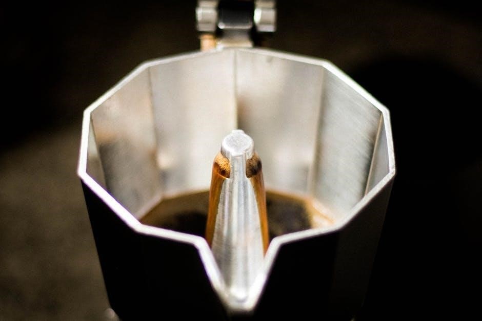
Black & Decker coffee makers feature several essential parts. The water reservoir holds the water for brewing, while the filter basket securely houses the coffee filter and grounds. The carafe, often glass or thermal, collects the brewed coffee.

The control panel manages brewing functions, including programming and auto-brew. Heating elements heat the water, and the spray head evenly distributes water over the grounds. Understanding these components aids in proper operation and maintenance, ensuring optimal coffee quality and longevity of the appliance.

Types of Black & Decker Coffee Makers (Drip, Single-Serve, Thermal)

Black & Decker offers a variety of coffee maker types. Drip coffee makers, like the CM1160B, are classic and brew multiple cups. Single-serve models, such as the CM618, provide individual portions for convenience.

Thermal coffee makers, including the CM2046S, utilize insulated carafes to maintain coffee temperature for extended periods. Each type caters to different needs, from large households to individual coffee drinkers, offering diverse brewing options.

Setting Up Your Coffee Maker

Proper setup involves initial cleaning, filling the water reservoir, and correctly placing a paper or reusable filter before the first brew for optimal performance.

Initial Cleaning Before First Use

Before your first delightful brew, thoroughly clean your Black & Decker coffee maker. Remove all packaging materials and wash the carafe, filter basket, and any detachable parts with warm, soapy water.

Rinse these components completely to eliminate any residue from the manufacturing process. Then, run a full brewing cycle with only water – no coffee grounds – to flush out the system.

This initial cleaning ensures a pure, fresh coffee taste and removes any potential odors, preparing your machine for years of enjoyable use. Discard the water after this cycle.

Water Reservoir Filling Instructions

To fill the water reservoir, carefully remove it from the coffee maker. Use fresh, cold, filtered water for optimal taste. Fill the reservoir to the desired cup level, referencing the water level indicator markings.

Avoid overfilling, as this can cause overflow during brewing. Once filled, securely reattach the reservoir to the coffee maker, ensuring it’s properly seated.

Proper water levels are crucial for achieving the correct coffee strength and preventing operational issues. Always use potable water.

Filter Placement: Paper vs. Reusable

Black & Decker coffee makers accommodate both paper filters and reusable filters. For paper filters, open the filter basket and insert a cone-shaped filter, ensuring it fits snugly. Reusable filters simply snap or slide into the designated filter basket area.

Ensure the filter is correctly positioned to prevent grounds from overflowing. Always rinse reusable filters thoroughly after each use. Proper filter placement is vital for clean brewing.

Using the correct filter type ensures optimal coffee flavor and prevents sediment in your cup.

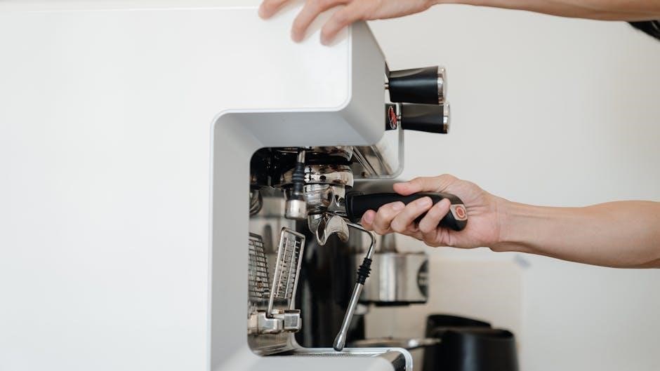
Brewing Coffee: A Step-by-Step Guide

Add desired coffee grounds to the filter, typically one scoop per cup. Fill the water reservoir, then press the brew button to start the process.

Utilize the 24-hour auto-brew timer for scheduled brewing, or the ‘Sneak-A-Cup’ feature for a quick serving.

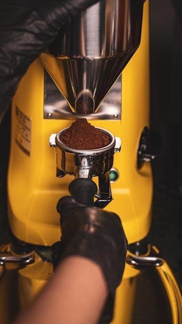
Adding Coffee Grounds: Recommended Amounts

Black & Decker coffee makers generally recommend one level scoop (approximately 5 tablespoons) of ground coffee per 12-cup carafe, adjusting to taste.

For smaller batches, proportionally reduce the amount of grounds; a good starting point is one tablespoon per cup. Experimenting is key to finding your ideal strength.

Finely ground coffee is best suited for drip machines, ensuring optimal extraction and flavor. Avoid overfilling the filter basket to prevent overflow and messy cleanup.

Consistent measurements yield consistent results, so consider using a dedicated coffee scoop for accuracy.

Programming the Auto-Brew Function (24-Hour Timer)

Black & Decker coffee makers with auto-brew functionality allow programming up to 24 hours in advance for fresh coffee upon waking.

Press the “Program” or “Timer” button, then use the “Hour” and “Minute” buttons to set the desired brew start time. Confirm your selection by pressing “Program” again.

Ensure the coffee maker is filled with water and grounds before setting the timer. The indicator light will illuminate, confirming the auto-brew is activated.

To cancel, simply press the “Program” button until the indicator light turns off.

Using the Sneak-A-Cup Feature

Many Black & Decker coffee makers include a “Sneak-A-Cup” feature, allowing you to pour a cup mid-brew without making a mess.

Simply remove the carafe briefly during the brewing cycle; the feature temporarily stops the drip to prevent spills onto the warming plate.

Replace the carafe within a reasonable timeframe (usually 30 seconds) to resume brewing. Note that using this feature may slightly alter brew strength.

This convenient function provides a quick caffeine fix before the full brewing process is complete.

Cleaning and Maintenance

Regular cleaning ensures optimal performance and longevity of your Black & Decker coffee maker; daily procedures, descaling, and carafe cleaning are essential.

Consistent upkeep prevents mineral buildup and maintains the quality of your brewed coffee.

Daily Cleaning Procedures

After each use, promptly discard used coffee grounds and the paper filter – or empty and rinse the reusable filter thoroughly.

Wash the carafe and filter basket with warm, soapy water, ensuring all coffee residue is removed; these parts are often dishwasher safe, but check your model’s manual.

Wipe down the exterior of the coffee maker with a damp cloth to prevent stains and maintain a clean appearance. Avoid abrasive cleaners, as they can damage the finish.

Regular daily cleaning prevents buildup and ensures consistently fresh-tasting coffee.

Descaling Your Coffee Maker

Descaling removes mineral buildup that affects performance and coffee taste. Fill the water reservoir with a mixture of equal parts white vinegar and water.

Run a full brewing cycle without coffee grounds. Repeat with fresh water 2-3 times to rinse away any vinegar residue thoroughly.

The frequency of descaling depends on water hardness; typically, every 3-6 months is recommended. Ignoring this can lead to slower brewing and potential damage.

Consult your model’s manual for specific descaling instructions.

Cleaning the Carafe and Filter Basket

After each use, wash the carafe and filter basket with warm, soapy water. For stubborn coffee stains in the carafe, a paste of baking soda and water can be effective.

Ensure all soap residue is rinsed away thoroughly. The carafe and filter basket are often dishwasher safe, but check your model’s manual first.

Regular cleaning prevents buildup and ensures optimal coffee flavor. Avoid abrasive cleaners that could scratch the surfaces.

Dry all components completely before reassembling.

Troubleshooting Common Issues

If the coffee maker won’t turn on, check the power cord and outlet. Slow brewing may indicate scaling; weak or bitter coffee needs adjustment.

Coffee Maker Not Turning On

If your Black & Decker coffee maker fails to power on, several checks are essential. First, ensure the power cord is securely plugged into a functioning electrical outlet.

Test the outlet with another device to confirm it’s providing power. Inspect the power cord itself for any visible damage, such as cuts or fraying.

If using an extension cord, verify it’s rated for the coffee maker’s wattage. A tripped circuit breaker could also be the culprit; check your electrical panel and reset if necessary.

Finally, consult the instruction manual for any specific reset procedures or safety features related to power interruption.

Coffee Brewing Too Slowly

If your Black & Decker coffee maker brews exceptionally slowly, scale buildup is a likely cause. Minerals from water accumulate over time, restricting water flow.

Descaling the coffee maker with a descaling solution or a vinegar-water mixture is crucial. Ensure the filter basket isn’t overfilled with coffee grounds, as this can also impede water flow.

Check for any obstructions in the water reservoir or spray head. A clogged spray head will significantly slow down the brewing process. Refer to your manual for cleaning instructions.

Regular cleaning and descaling prevent this issue and maintain optimal brewing speed.

Coffee Tastes Weak or Bitter

Weak coffee often results from insufficient coffee grounds. Increase the amount of coffee used per cup, following the recommended guidelines in your instruction manual.

Bitter coffee can stem from using too much coffee, stale grounds, or a dirty coffee maker. Ensure you’re using fresh, quality coffee beans and cleaning the machine regularly.

Descaling removes mineral buildup that can affect taste. Experiment with brew strength settings, if available, to find your preferred flavor profile.

Water quality also impacts taste; use filtered water for best results.

Advanced Features & Settings

Black & Decker coffee makers offer programmable brew strength and adjustable keep-warm temperatures, allowing customization for optimal flavor and personalized brewing experiences.

Programmable Brew Strength

Black & Decker coffee makers with this feature allow users to tailor the coffee’s intensity to their liking. Typically, this is controlled via a ‘Brew Strength’ button on the control panel.

Options usually include ‘Regular’ for a standard brew, and ‘Bold’ for a richer, more robust flavor. Selecting ‘Bold’ often slows the brewing process slightly, ensuring maximum extraction from the coffee grounds.

Consult your specific model’s instruction manual for precise settings and operation, as button labels and functionality can vary between different Black & Decker designs.

Adjusting the Keep-Warm Temperature

Many Black & Decker coffee makers feature a keep-warm function to maintain coffee temperature after brewing. While not all models offer adjustable temperatures, some allow customization.

If available, this setting is usually accessed through the control panel, potentially with ‘Low,’ ‘Medium,’ and ‘High’ options. Lower settings preserve flavor longer, while higher settings ensure maximum warmth.

Refer to your specific model’s instruction manual for detailed guidance, as the keep-warm duration and temperature controls vary significantly between different Black & Decker designs.

Safety Precautions

Black & Decker coffee makers require electrical safety adherence, avoiding water exposure and damaged cords. Prevent burns by handling hot surfaces carefully and using caution with steam.

Electrical Safety Guidelines

Always ensure the coffee maker is plugged into a grounded outlet with the correct voltage to prevent electrical shock or fire hazards. Never operate the appliance with a damaged cord or plug; replace immediately.

Do not immerse the coffee maker, cord, or plug in water or other liquids. Avoid using extension cords, but if necessary, use a heavy-duty cord rated for the appliance’s wattage.

Unplug the coffee maker from the outlet when not in use and before cleaning. Inspect the cord regularly for damage, and never attempt to repair it yourself – seek professional assistance.

Avoiding Burns and Scalds

Exercise caution when handling the carafe, as it becomes hot during and after brewing. Always use the handle or a pot holder to avoid burns. Be mindful of escaping steam, especially when opening the lid or removing the carafe.

Never touch hot surfaces, and keep children away from the coffee maker during operation. Allow the appliance to cool completely before cleaning or storing. Avoid spilling hot coffee, and clean up any spills immediately.

Do not operate the coffee maker if the carafe is cracked or damaged, as this could lead to scalding.

Replacement Parts & Accessories

Black & Decker offers compatible replacement parts for various models, including carafes and filters, ensuring longevity and continued optimal performance of your coffee maker.

Finding Compatible Parts for Your Model

Locating the correct replacement parts for your Black & Decker coffee maker is crucial for maintaining its functionality. Begin by identifying your specific model number, typically found on the appliance’s underside or in the instruction manual.

Once you have the model number, you can search online retailers or the Black & Decker website for compatible parts lists and diagrams. These resources often include photos to aid in accurate identification. Parts are available for 64 models.

Ensure the part number matches before purchasing to guarantee a proper fit and function.

Carafe Replacements

Replacing a broken carafe is often necessary to continue enjoying your Black & Decker coffee maker. Carafes are model-specific, so knowing your appliance’s model number is essential for finding a compatible replacement.

Glass carafes are common, but thermal carafes are also available for models like the CM2046S, offering extended heat retention. Online retailers and the Black & Decker website are excellent sources.

Always verify the carafe’s capacity and handle style match your original before ordering.

Black & Decker Coffee Maker Models Comparison

Black & Decker offers diverse models, including the CM1160B drip coffee maker and the DLX1050 programmable version, each with unique features and capacities.

CM1160B Model Details

The Black & Decker CM1160B is a classic drip coffee maker constructed with plastic and stainless steel components, finished in a sleek black and silver color scheme;

This model is designed for simplicity and reliability, offering a straightforward brewing process without complex features. It’s ideal for users seeking a no-frills, dependable coffee maker.

While lacking advanced programmability, the CM1160B consistently delivers a pot of coffee, making it a practical choice for everyday use in homes or small offices.

DLX1050 Model Features

The Black & Decker DLX1050 is a 12-cup programmable coffee maker with a glass carafe, designed to deliver a satisfying coffee experience without a premium price.

Key features include a 24-hour auto-brew function, allowing users to schedule coffee preparation in advance, and a ‘Sneak-A-Cup’ feature for interrupting the brewing cycle.

Its programmable timer and user-friendly design make it a convenient option for those seeking a reliable and customizable coffee maker for daily use.

Understanding the Control Panel

Black & Decker control panels feature buttons for power, programming, and brew strength, alongside display indicators showing brewing status and timer settings for ease of use.

Button Functions Explained

Power initiates or halts the brewing cycle, while the Program button sets the 24-hour auto-brew timer, allowing for pre-scheduled coffee preparation. The Brew Strength button, available on select models, adjusts coffee flavor intensity.

Sneak-A-Cup temporarily pauses brewing for a quick serving, and other buttons may control cleaning cycles or adjust keep-warm settings. Illuminated indicators confirm selected functions.

Refer to your specific model’s instruction manual for detailed explanations of each button’s operation, ensuring optimal use and customization of your Black & Decker coffee maker.

Display Indicators and Their Meanings

The clock display shows the current time, while a timer indicator illuminates when the auto-brew function is activated. A brew indicator signals active coffee making, and a keep-warm light confirms the warming plate is engaged.

Some models feature indicators for strength selection or cleaning cycles. Flashing lights often signify errors or the need for attention, like descaling.

Consult your specific Black & Decker coffee maker’s manual for a comprehensive understanding of all display symbols and their corresponding meanings.

Warranty Information

Black & Decker coffee makers come with a limited warranty covering manufacturing defects. Warranty duration varies by model; check your documentation for details and claim procedures.

Retain your proof of purchase for warranty service requests, ensuring a smooth process if issues arise with your appliance.

Black & Decker Coffee Maker Warranty Coverage

Black & Decker typically offers a one-year limited warranty on their coffee makers, covering defects in materials and workmanship from the date of purchase.

This warranty doesn’t cover damage from misuse, accidents, or unauthorized repairs. Normal wear and tear, like carafe breakage, isn’t usually included.

The warranty ensures repair or replacement (at Black & Decker’s discretion) of defective parts, excluding shipping costs. Proof of purchase is essential for any claim.

Specific terms and conditions can vary, so always refer to the warranty documentation included with your particular model for complete details.

How to Claim Warranty Service

To initiate a warranty claim for your Black & Decker coffee maker, first, retain your proof of purchase – a receipt or date on the instruction manual.

Contact Black & Decker’s customer service via their website or phone number, detailing the issue and providing your model number.

They may request photos or a return of the defective unit for inspection. Shipping costs are generally the consumer’s responsibility.

Upon verification, Black & Decker will either repair or replace the coffee maker, based on their assessment and warranty terms.

Tips for Optimal Coffee Brewing

Utilize freshly ground coffee beans for richer flavor, and ensure high-quality water, as it significantly impacts the final taste of your brewed coffee.

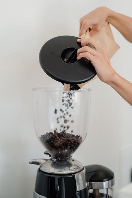
Using Freshly Ground Coffee Beans

For the most flavorful cup, always opt for freshly ground coffee beans instead of pre-ground varieties. Grinding beans immediately before brewing unlocks their aromatic oils and delivers a superior taste experience.

A burr grinder is recommended for consistent particle size, crucial for even extraction. Experiment with grind settings – a medium grind generally works best for Black & Decker drip coffee makers.

Storing beans in an airtight container, away from light, heat, and moisture, preserves their freshness and extends their shelf life, ensuring optimal brewing results every time.

Water Quality and Its Impact on Taste

The quality of water significantly impacts the final taste of your coffee. Black & Decker coffee makers perform best with filtered water, as tap water often contains chlorine and minerals that can detract from the coffee’s natural flavors.

Using filtered water ensures a cleaner, brighter, and more nuanced cup. Avoid distilled water, as it lacks the minerals needed for optimal extraction. Regularly clean your coffee maker to prevent mineral buildup.

Good water equals good coffee – a simple step for a noticeably improved brewing experience.

Black & Decker Coffee Maker FAQs

Frequently asked questions cover cleaning, programming the auto-brew, troubleshooting slow brewing, and understanding display indicators on Black & Decker coffee makers.

Frequently Asked Questions and Answers

Q: Why won’t my coffee maker turn on? Ensure the unit is plugged in and the outlet is working. Check the power cord for damage.

Q: Coffee brews slowly? Descale the machine; mineral buildup restricts water flow. Use the recommended coffee-to-water ratio.

Q: Coffee tastes weak? Increase the amount of coffee grounds used. Select a stronger brew setting if available. Ensure fresh coffee is used.

Q: How do I program the auto-brew? Refer to your instruction manual for specific steps, typically involving setting the desired brew time.

navien npe-240s2 manual

Navien NPE-240S2 Manual: A Comprehensive Guide

This detailed manual covers installation, operation, and maintenance for Navien NPE-180A2, NPE-150S2, and NPE-240S2 tankless water heaters, offering comprehensive guidance.

The Navien NPE-240S2 is a high-efficiency, condensing tankless water heater designed to provide endless hot water on demand. This model, alongside the NPE-180A2 and NPE-150S2, represents Navien’s commitment to innovative and reliable home comfort solutions. Unlike traditional tank water heaters, the NPE-240S2 heats water only when needed, eliminating standby heat loss and significantly reducing energy consumption.

This manual serves as a complete resource for understanding, installing, operating, and maintaining your NPE-240S2. It’s crucial to thoroughly review this guide before attempting any installation or maintenance procedures. The NPE-240S2 continuously operates, resulting in a constant flow through the condensate drain line, a key characteristic of condensing technology. Proper installation and regular maintenance, as detailed within, are vital for optimal performance and longevity. This guide will empower both professionals and DIY enthusiasts to maximize the benefits of their Navien tankless water heater.

Understanding Tankless Water Heaters

Tankless water heaters, unlike conventional storage tank models, heat water directly without the need for a reservoir. This “on-demand” heating provides a continuous supply of hot water, eliminating the energy waste associated with maintaining a constantly heated tank. Navien’s NPE series, including the NPE-240S2, utilizes condensing technology, extracting additional heat from exhaust gases for even greater efficiency.

This technology results in lower operating costs and reduced environmental impact. Tankless systems are also space-saving, as they mount on a wall and don’t require the large footprint of a traditional tank. Understanding the principles of tankless operation – specifically the flow activation and precise temperature control – is key to maximizing the benefits of your Navien NPE-240S2. Proper sizing and installation are crucial to ensure adequate hot water delivery for your household’s needs.

Safety Precautions

Important: Installation and maintenance of the Navien NPE-240S2 should only be performed by qualified technicians. Always disconnect gas and electrical power before servicing. Carbon monoxide (CO) is a dangerous byproduct of combustion; ensure proper ventilation and install CO detectors in accordance with local codes. Never obstruct the air intake or exhaust vents.

Exercise caution when handling the unit, as surfaces may become hot during operation. Avoid contact with the condensate drain line, as the condensate is acidic. Proper grounding is essential to prevent electrical shock. Always follow local plumbing and gas codes during installation. Regularly inspect the unit for leaks or damage. Failure to adhere to these safety precautions could result in fire, explosion, carbon monoxide poisoning, or personal injury. Prioritize safety throughout the entire process.

Installation Guide

This section details the proper procedures for unpacking, mounting, connecting gas and water lines, and preparing the Navien NPE-240S2 for operation.

Unpacking and Inspection

Upon receiving your Navien NPE-240S2, carefully inspect the shipping carton for any signs of damage incurred during transit. If damage is visible, immediately document it with photographs and file a claim with the carrier. Carefully open the carton and verify that all components are present. The package should include the NPE-240S2 unit itself, mounting hardware, installation accessories, and this comprehensive installation manual.

Thoroughly inspect the unit for any cosmetic damage, such as scratches or dents. More importantly, check for any damage to the gas connection fittings, water connections, or the control panel. Ensure the unit’s nameplate is securely attached and legible, as it contains crucial information regarding the model number, serial number, and gas type. Retain all packaging materials until you have confirmed the unit is functioning correctly and are satisfied with the installation. Proper inspection now can prevent issues later.

Wall Mounting Procedures

Prior to mounting, confirm the wall is structurally sound and capable of supporting the weight of the NPE-240S2, especially when filled with water. Locate the desired mounting position, ensuring adequate clearance for servicing and ventilation as specified in the installation guide. Using the provided mounting template, mark the locations for the mounting holes on the wall. Drill pilot holes at the marked locations, ensuring they are appropriate for the wall material.

Securely attach the mounting bracket to the wall using appropriate fasteners – screws and wall anchors are typically included. Carefully lift the NPE-240S2 onto the mounting bracket, ensuring it is properly seated and locked into place. Double-check that the unit is level and securely fastened to the bracket. Improper mounting can lead to instability and potential safety hazards, so verify all connections before proceeding with further installation steps.

Removing the Front Cover

Before accessing internal components for installation or maintenance, safely remove the front cover of the Navien NPE-240S2. Begin by ensuring the unit is powered off at the breaker to prevent electrical shock. Locate the release clips or screws securing the front cover – these are typically positioned along the top and sides of the unit. Gently depress or unscrew these fasteners, taking care not to force them.

Once all fasteners are released, carefully pull the front cover forward and away from the unit. It may require a slight wiggle to disengage completely. Avoid pulling on any wires or connections visible behind the cover. Store the front cover in a safe place during servicing to prevent damage. Remember to reattach the cover securely after completing any internal work, ensuring all fasteners are properly engaged.

Gas Line Connections

Proper gas line connection is crucial for safe and efficient operation of the Navien NPE-240S2. Always adhere to local gas codes and regulations. Before connecting, ensure the gas supply is turned off at the main valve. Use only black iron pipe or approved flexible gas connectors, applying pipe joint compound suitable for gas lines to all threaded connections.

Verify the gas type (natural gas or propane) matches the unit’s configuration. Incorrect gas type can cause malfunction and pose a safety hazard. A qualified technician should perform these connections, checking for leaks using a soap solution after completion. Securely tighten all fittings to prevent gas leakage. Improper connections can lead to fire or explosion, so meticulous attention to detail is paramount.

Natural Gas Connection

When connecting to a natural gas supply, ensure the gas pressure meets the specifications outlined in the Navien NPE-240S2’s technical data. Typically, this requires a pressure of 7 inches of water column (W.C.). Utilize a properly sized gas pipe, determined by the BTU input of the unit and the length of the gas line, to maintain adequate pressure.

A manual shut-off valve should be installed upstream of the unit for easy access during maintenance or emergencies. Thoroughly inspect the gas line for any damage or corrosion before making connections. Apply gas-rated pipe dope to all threaded joints, ensuring a leak-proof seal. After connection, perform a leak test with a soap solution, carefully checking all fittings and connections.

Propane Gas Conversion & Dipswitch Settings

Converting the Navien NPE-240S2 from natural gas to propane requires adjusting the dipswitches located on the control board. Carefully consult the unit’s wiring diagram to identify the correct dipswitch positions for propane operation. Typically, this involves changing settings related to the gas valve and ignition system to accommodate propane’s different combustion characteristics.

Before making any changes, disconnect power to the unit. After adjusting the dipswitches, a qualified technician must verify proper operation and adjust the combustion parameters. Ensure the propane tank is adequately sized for the unit’s BTU input and that a properly sized regulator is installed. Failure to correctly configure the dipswitches and combustion settings can result in unsafe operation.

Water Line Connections

Establishing proper water line connections is crucial for the Navien NPE-240S2’s performance and longevity. Use dielectric unions to connect copper or CPVC piping to the unit, preventing corrosion from galvanic reactions. Ensure all connections are watertight using Teflon tape or pipe dope specifically designed for potable water systems. Flush the water lines thoroughly before connecting to remove debris that could damage the heat exchanger.

Pay close attention to the inlet and outlet designations; incorrect connections will impede proper operation. Consider installing shut-off valves on both the inlet and outlet lines for easy maintenance and future repairs. Proper pipe support is essential to prevent stress on the unit’s connections.

Inlet and Outlet Connections

The Navien NPE-240S2 features clearly marked inlet and outlet connections, typically ¾-inch NPT. The cold water inlet, usually blue, connects to your main water supply. The hot water outlet, often red, delivers heated water to your home’s plumbing. Always use dielectric unions when connecting copper or CPVC piping to prevent corrosion.

Ensure proper pipe sizing to maintain adequate water pressure and flow rate. Incorrectly sized pipes can lead to reduced hot water performance. Before making final connections, thoroughly flush the water lines to remove any sediment or debris. Double-check all connections for leaks after installation and initial startup, tightening as needed.

Pressure Relief Valve Installation

A crucial safety component, the pressure relief valve (PRV) must be installed correctly; Locate the designated port on the Navien NPE-240S2 for PRV connection. Use Teflon tape on the threads to ensure a watertight seal. The PRV’s discharge pipe must be the same diameter as the valve outlet and constructed of an approved material like copper or CPVC.

This discharge pipe should terminate within 6 inches of the floor, allowing for visible discharge in case of activation. It must not be threaded, capped, or reduced in size, and should never point towards areas where it could cause scalding. Regularly inspect the PRV and discharge pipe for corrosion or damage, replacing them as needed to maintain safety.

Operation and User Interface

The Navien NPE-240S2 features an intuitive control panel for adjusting settings, monitoring error codes, and optimizing hot water temperature for efficient usage.

Control Panel Overview

The Navien NPE-240S2’s control panel serves as the central hub for managing your tankless water heating system. It features a user-friendly interface with several key indicators and controls. The display screen prominently shows the current outlet water temperature, allowing for quick monitoring of your hot water supply. Buttons enable adjustments to the desired temperature, typically within a range of 85°F to 140°F, catering to various household needs and preferences.

Several indicator lights provide crucial system status information. These include lights for power, flame detection, and error codes. The error code display is particularly important, as it signals potential issues requiring attention. Additional buttons may facilitate functions like setting comfort mode, scheduling operation, or initiating descaling cycles. Familiarizing yourself with the control panel’s layout and functions is essential for efficient operation and troubleshooting of your Navien NPE-240S2 unit. Refer to the full manual for detailed explanations of each button and indicator.

Understanding Error Codes

The Navien NPE-240S2 utilizes error codes as a diagnostic tool, signaling potential problems within the system. These codes appear on the control panel display and are crucial for effective troubleshooting. Each code corresponds to a specific issue, ranging from minor inconveniences to more serious malfunctions. Common error codes might indicate issues with flame detection, gas supply, water flow, or internal component failures.

It’s vital not to ignore error codes. The manual provides a comprehensive list detailing each code’s meaning and suggested corrective actions. Some errors can be resolved by simple user interventions, like resetting the unit. However, others necessitate professional service. Ignoring persistent error codes can lead to further damage or compromise the unit’s performance and safety. Always consult the manual’s error code section before attempting any repairs, and when in doubt, contact a qualified technician for assistance.

Adjusting Water Temperature

The Navien NPE-240S2 allows precise control over your hot water temperature, ensuring comfort and energy efficiency. Temperature adjustment is typically performed via the control panel, utilizing the up and down arrow buttons. The display will show the currently set temperature, usually ranging from 85°F to 140°F. It’s crucial to find a balance – too low, and you risk insufficient hot water; too high, and scalding becomes a concern.

Consider your household’s needs when setting the temperature. Lower temperatures conserve energy, but higher temperatures are beneficial for dishwashers requiring hotter water. The manual recommends a setting of 120°F for general use. Incremental adjustments are best; increase or decrease the temperature in small steps and allow time to assess the results. Remember safety first – protect vulnerable individuals from potential scalding by setting a reasonable maximum temperature.

Hot Water Usage Tips

Maximizing the efficiency of your Navien NPE-240S2 involves mindful hot water usage. Avoid running hot water unnecessarily; even short bursts contribute to energy waste. Fix any leaky faucets promptly, as drips add up over time. When using multiple hot water appliances simultaneously – showers, dishwashers, washing machines – be aware that the unit’s capacity has limits. Staggering usage can prevent a drop in water temperature.

Consider installing low-flow showerheads and faucet aerators to reduce water consumption without sacrificing pressure. Regularly flush your hot water lines to remove sediment buildup, ensuring optimal performance. The NPE-240S2’s on-demand heating eliminates standby heat loss, but efficient habits further enhance savings. Monitor your water bill for any unexpected increases, which could indicate a problem.

Maintenance and Troubleshooting

Regular upkeep, including descaling and condensate drain line checks, ensures peak performance. Addressing common issues like no hot water or low pressure is crucial.

Regular Maintenance Schedule

To ensure the longevity and efficient operation of your Navien NPE-240S2 tankless water heater, a consistent maintenance schedule is paramount. It’s recommended to visually inspect the unit monthly, checking for any leaks or unusual noises. A crucial aspect is annual descaling, particularly in areas with hard water, to prevent mineral buildup that reduces heating efficiency and potentially damages components.

The condensate drain line requires attention every six months; flush it with water to remove any obstructions and ensure proper drainage. Additionally, inspect the air intake and exhaust vents for blockages, ensuring adequate ventilation. A professional inspection by a qualified technician is advised every two years to assess overall system health, check gas connections, and verify proper combustion. Following this schedule will help maintain optimal performance and prevent costly repairs, maximizing the lifespan of your Navien NPE-240S2.

Descaling Procedures

Regular descaling is vital for maintaining the Navien NPE-240S2’s efficiency, especially with hard water. Begin by turning off the gas and power supply to the unit. Locate the descaling port – consult your installation guide for its precise location. Connect a submersible pump and hose to the port, placing the hose end into a suitable descaling solution (follow manufacturer’s recommendations for compatible solutions).

Initiate the descaling cycle through the unit’s control panel, typically a dedicated “Descaling” mode. Allow the solution to circulate for the recommended duration, usually between 30 to 60 minutes, depending on the level of scale buildup. After the cycle, flush the system with clean water until it runs clear, ensuring all traces of the descaling solution are removed. Restore power and gas, and test the unit’s operation. Repeat annually, or more frequently if water hardness is exceptionally high.

Condensate Drain Line Maintenance

The Navien NPE-240S2, being a condensing unit, continuously produces condensate. Regular maintenance of the drain line is crucial to prevent blockages and potential damage. Inspect the drain line – typically PVC – at least twice yearly for kinks, clogs, or signs of freezing. Ensure the drain line has a proper trap to prevent sewer gases from entering the unit.

Periodically flush the drain line with warm water and a mild vinegar solution to dissolve any buildup. Avoid using harsh chemicals that could damage the line or the unit’s components. Check the termination point of the drain line to confirm it’s unobstructed and draining correctly. If algae growth is present, consider using a condensate pan tablet designed for HVAC systems. Addressing drain line issues promptly will ensure optimal performance and longevity of your Navien water heater.

Troubleshooting Common Issues

Several issues can arise with the Navien NPE-240S2. If you experience No Hot Water, verify the unit is powered on and the gas supply is active. Check for error codes on the control panel. Low Hot Water Pressure can stem from partially closed valves, a clogged filter, or scale buildup within the unit – descaling may be necessary.

Error Code Resolution requires referencing the error code list in this manual. Common codes indicate issues with flame detection, water flow, or venting. Before attempting repairs, ensure the unit is de-energized. If you’re uncomfortable with any troubleshooting step, contact a qualified technician. Ignoring error codes or attempting complex repairs yourself could void the warranty and potentially cause further damage. Always prioritize safety and consult professional help when needed.

No Hot Water

Experiencing no hot water from your Navien NPE-240S2 can be frustrating. First, confirm the unit is receiving power and isn’t in standby mode. Check the control panel for any displayed error codes, as these provide valuable diagnostic information. Verify the gas supply valve is fully open and that there isn’t a disruption in gas service.

Inspect the water supply lines to ensure they are fully open and free of kinks or obstructions. A lack of incoming water can prevent the unit from firing. If the unit attempts to ignite but fails, there may be an issue with the flame sensor or ignition system. Consult the error code section of this manual for specific troubleshooting steps related to ignition failures. If problems persist, contact a qualified technician.

Low Hot Water Pressure

If you’re experiencing low hot water pressure with your Navien NPE-240S2, several factors could be at play. Begin by checking the inlet water pressure to the unit; it must meet the manufacturer’s specifications for optimal performance. Partially or fully closed shut-off valves on the water supply lines will restrict flow, so ensure they are fully open.

Inspect the inlet and outlet pipes for any obstructions or kinks that might be limiting water flow. Sediment buildup within the unit’s heat exchanger can also reduce pressure; descaling procedures, detailed elsewhere in this manual, may be necessary. If the issue persists, verify that other plumbing fixtures aren’t simultaneously demanding high water flow, which could lower pressure to the Navien unit.

Error Code Resolution

The Navien NPE-240S2 utilizes error codes to diagnose potential issues. When an error code appears on the control panel, consult the detailed error code list within this manual for a specific explanation. Common codes relate to flame detection, water flow, or gas supply problems.

For flame detection errors, verify the gas supply is active and the unit is properly vented. Water flow errors often indicate insufficient incoming water pressure or a blockage in the system. Gas supply errors may require professional assistance to diagnose and resolve. Attempting a reset of the unit, by power cycling, can sometimes clear temporary errors.

If the error persists after troubleshooting, record the code and contact a qualified Navien technician for further assistance. Do not attempt repairs beyond your expertise.

Technical Specifications

This section details the NPE-240S2’s dimensions, performance data, and warranty details, providing essential technical information for installation and service professionals.

NPE-240S2 Dimensions

Understanding the physical dimensions of the Navien NPE-240S2 is crucial for proper installation planning and ensuring adequate space allocation within the designated installation area. Precise measurements are essential to avoid any potential obstructions or conflicts with surrounding structures or utilities. The unit’s height, width, and depth must be carefully considered during the initial assessment phase.

Detailed dimensional drawings are typically included within the full installation manual, providing a comprehensive visual representation of the unit’s footprint. These drawings illustrate key mounting points and connection locations, facilitating accurate placement and alignment. It’s important to verify these dimensions against the available space to confirm compatibility before commencing the installation process. Accurate measurements contribute to a safe and efficient installation, maximizing the unit’s performance and longevity.

Consult the official Navien documentation for the most up-to-date and precise dimensional specifications for the NPE-240S2 model.

NPE-240S2 Performance Data

The Navien NPE-240S2 boasts impressive performance capabilities, delivering a substantial volume of hot water on demand. Key performance indicators include its maximum flow rate, measured in gallons per minute (GPM), and its temperature rise capability, indicating how much the water temperature can be increased during operation. Understanding these metrics is vital for matching the unit to household hot water demands.

Efficiency is another critical aspect of the NPE-240S2’s performance, reflected in its Uniform Energy Factor (UEF) rating. A higher UEF signifies greater energy savings and reduced operating costs. The unit’s ability to maintain consistent hot water delivery, even during periods of high demand, is a testament to its robust design and advanced technology. Detailed performance charts and specifications are available in the official Navien documentation.

These data points allow for informed decisions regarding suitability for specific applications and household sizes.

Warranty Information

Navien provides a comprehensive warranty on the NPE-240S2 tankless water heater, demonstrating their commitment to product quality and customer satisfaction. The standard warranty typically covers parts and labor for a specified period, often differing based on registration status and installation by a certified professional.

Registering the product promptly after installation is crucial to activate the full warranty benefits. The warranty safeguards against defects in materials and workmanship under normal use. However, it generally doesn’t cover issues arising from improper installation, misuse, or lack of required maintenance, such as descaling.

Detailed warranty terms and conditions, including specific coverage durations and exclusions, are outlined in the official Navien warranty documentation. Retaining proof of purchase and installation records is essential for any warranty claims.

emerson tv user manual

Emerson TV User Manual: A Comprehensive Guide

Welcome! This manual details setup, features, troubleshooting, and specifications for your Emerson TV, including Smart TV and vintage models like the EWV401B.

Congratulations on choosing an Emerson television! This section introduces you to the diverse range of Emerson TV products, from modern Smart TVs with network connectivity to classic models. Whether you have a 32-inch LCD TV or are exploring features of the TX series with integrated sensors and electromagnetic valves, this manual provides essential guidance.

Emerson offers solutions for both home entertainment and commercial applications, including the ESM series for energy metering updated for 2026. We’ll cover everything from initial setup and remote control operation to navigating the on-screen menu and troubleshooting common issues, ensuring a seamless viewing experience.

Unboxing and Initial Setup

Carefully unpack your new Emerson TV, ensuring all components are present. This includes the TV itself, the remote control, any included stands or mounting hardware, and this user manual. Inspect for any visible damage sustained during shipping. Before connecting cables, position the TV in your desired location, ensuring adequate ventilation.

Connect the power cord to a grounded outlet. For Smart TVs, initial setup will guide you through connecting to your Wi-Fi network or Ethernet. Refer to the ‘Network Connectivity’ section for detailed instructions. Ensure the TV is powered off during all connections.

Remote Control Overview

Your Emerson TV remote is your primary interface for controlling all functions. Familiarize yourself with the button layout before use. Key buttons include power, volume control, channel selection, menu navigation, and input source selection. Dedicated buttons may exist for streaming services on Smart TV models.

The remote may require pairing with the TV, especially after battery replacement. See the ‘Remote Control Pairing’ section for instructions. Ensure the battery compartment is securely closed. Proper remote operation is crucial for a seamless viewing experience.

Understanding the Buttons

The power button turns the TV on and off. Volume buttons adjust the sound level. Channel up/down navigate through available channels. The menu button accesses the on-screen display for settings adjustments. Input/Source selects different connected devices (HDMI, USB, AV).

Navigation buttons (arrow keys) move within menus. OK/Enter confirms selections. Back/Return navigates to the previous screen. Dedicated buttons for streaming apps launch those services directly. Refer to the full remote control overview for a complete button function list.

Remote Control Pairing

For initial setup or after battery replacement, pairing may be required. Ensure the TV is powered on. Press and hold the ‘Return’ and ‘Back’ buttons simultaneously for three seconds. The TV will display a pairing message. If automatic pairing fails, navigate to the settings menu using the TV’s physical buttons.

Select ‘Remote & Accessories’ and choose ‘Pair Remote’. Follow the on-screen instructions. A successful pairing will be indicated by an on-screen confirmation. If issues persist, replace the remote’s batteries and repeat the process.

Connecting External Devices

Enhance your viewing experience by connecting devices like Blu-ray players, gaming consoles, and streaming devices. Utilize the available HDMI ports for high-definition audio and video transmission. USB ports allow for media playback from compatible storage devices. For older devices, AV (composite) connections are also supported, though picture quality may be reduced.

Ensure the TV is powered off before connecting or disconnecting any devices. Refer to the device’s manual for specific connection instructions. Properly connected devices will automatically be detected by the TV.

HDMI Connections

HDMI (High-Definition Multimedia Interface) provides the best possible picture and sound quality. Locate the HDMI ports on the rear or side of your Emerson TV. Connect your Blu-ray player, game console, or streaming device using a high-speed HDMI cable.

Once connected, use the TV’s input source selection to choose the corresponding HDMI port. The TV automatically detects most HDMI devices. For optimal performance, ensure the connected device’s output resolution matches your TV’s native resolution.

USB Connections

USB ports on your Emerson TV allow you to connect external storage devices like flash drives or external hard drives. This enables you to play media files such as photos, videos, and music directly on your TV screen.

Simply plug the USB device into a USB port. Navigate to the media player app on your TV’s menu to access the files. Supported file formats may vary; consult the TV’s specifications for details. Ensure the USB drive is formatted with a compatible file system (FAT32 or NTFS).

AV (Composite) Connections

AV, or composite, connections utilize a set of RCA cables – typically yellow for video and red/white for audio – to connect older devices like VCRs (such as the Emerson EWV401B) or DVD players to your TV.

Match the colored plugs to the corresponding input jacks on your TV. Select the “AV” input source on your TV using the remote control. Image quality via composite connections is generally lower than HDMI. Ensure cables are securely connected for optimal signal transmission and a clear picture.

Navigating the On-Screen Menu

Accessing the menu is simple: press the “Menu” button on your Emerson remote. The on-screen display allows customization of your viewing experience. Explore options for Picture Settings (brightness, contrast, color), Sound Settings (volume, equalizer, sound mode), and Channel Settings (auto scan, manual scan, favorite channels).

Use the arrow keys to navigate and the “OK” or “Enter” button to select. Remember to save any changes before exiting the menu to ensure your preferences are retained.

Picture Settings

Customize your viewing experience within the Picture Settings menu. Adjust Brightness for optimal clarity, Contrast to define image depth, and Color saturation for vibrant visuals. Explore preset modes like “Standard,” “Movie,” or “Vivid” for quick adjustments.

Advanced users can fine-tune Sharpness, Tint, and Color Temperature. A 32-inch LCD TV’s specifications are impacted by these settings. Experiment to find the perfect balance for your environment and content, ensuring a comfortable and immersive viewing experience.

Sound Settings

Optimize your audio using the Sound Settings menu. Adjust the Volume for desired loudness, and explore Equalizer options to customize sound frequencies. Select preset sound modes like “Standard,” “Music,” or “Movie” for tailored audio experiences.

Further refine your audio with settings like Treble and Bass control. Some models may offer Surround Sound simulation. Ensure balanced audio for all content, complementing the visual experience of your Emerson TV, including those with TX series features.

Channel Settings

Manage your channels efficiently through the Channel Settings menu. Perform Automatic Channel Scan to locate available over-the-air broadcasts, or utilize Manual Channel Scan for specific frequencies. Organize channels with Channel Editing – delete unwanted channels or reorder them for convenient access.

Explore features like Favorite Channels for quick viewing. Ensure proper signal strength for optimal reception. These settings apply to the built-in tuner, enhancing your viewing experience, whether using a 32-inch LCD TV or a newer Emerson TX series model.

Using the Built-in Tuner

Accessing Channels is simple with the built-in tuner. Begin by selecting the ‘Channel’ menu option. You can then initiate an Automatic Channel Scan to discover all available over-the-air digital and analog channels in your area. Alternatively, employ the Manual Channel Scan feature to input specific channel frequencies, useful for accessing less common broadcasts.

Ensure a properly connected antenna for optimal signal reception. The tuner supports various signal standards, providing a comprehensive viewing experience across Emerson TV models, including the TX series.

Automatic Channel Scan

Initiating the Scan: From the ‘Channel Settings’ menu, select ‘Automatic Channel Scan’. Your Emerson TV will automatically search across available frequencies for broadcast channels. This process may take several minutes, depending on signal strength and the number of channels available in your region.

Optimizing Results: Ensure a securely connected antenna before starting the scan. The TV will store discovered channels, allowing easy access. Repeat the scan if channel lineups change or after repositioning your antenna for improved reception. This feature works across all Emerson TV models.

Manual Channel Scan

Accessing Manual Scan: Within the ‘Channel Settings’ menu, choose ‘Manual Channel Scan’. You’ll be prompted to enter a specific channel frequency or channel number. This is useful for locating channels not found during an automatic scan, or for fine-tuning reception of weaker signals;

Inputting Frequencies: Carefully input the correct frequency for your desired channel. Scan through available frequencies incrementally. Save each discovered channel to your channel list. This method requires knowledge of local broadcast frequencies for optimal results across all Emerson TV series.

Network Connectivity (Smart TVs)

Connecting to the Internet: Your Emerson Smart TV requires a network connection for streaming services and updates. Access the ‘Network’ settings within the on-screen menu. You can connect via Wi-Fi or Ethernet. For Wi-Fi, select your network and enter the password. Ensure a strong signal for optimal performance.

Ethernet Connection: Alternatively, connect an Ethernet cable directly to your router for a stable, wired connection. The TV will automatically detect the connection. Verify successful connection status within the network settings. Enjoy seamless access to online content!

Connecting to Wi-Fi

Wireless Setup: To connect your Emerson Smart TV to Wi-Fi, navigate to the ‘Network’ section in the settings menu. Select ‘Wi-Fi’ and the TV will scan for available networks. Choose your network from the list and enter your password using the on-screen keyboard.

Troubleshooting: If the connection fails, ensure you’ve entered the correct password and that your router is functioning correctly. Try restarting both the TV and the router. A strong Wi-Fi signal is crucial for smooth streaming.

Ethernet Connection

Wired Network: For a stable connection, use an Ethernet cable to connect your Emerson Smart TV directly to your router. Navigate to the ‘Network’ settings and select ‘Ethernet’. The TV should automatically detect the connection and obtain an IP address.

Benefits: An Ethernet connection generally provides a faster and more reliable internet experience compared to Wi-Fi, ideal for streaming high-definition content. If you experience Wi-Fi issues, a wired connection is a recommended alternative.

Troubleshooting Common Issues

Facing problems? This section addresses frequent concerns. No Picture: Check power, input source, and cable connections. No Sound: Verify volume levels, mute status, and audio output settings. Remote Not Working: Replace batteries, ensure line-of-sight, and attempt re-pairing (see ‘Remote Control Pairing’).

Further Assistance: If issues persist, consult the full manual or contact Emerson Customer Support at +7 (351) 799 51 51 for dedicated help. Detailed solutions for various scenarios are available online at info.metranemerson.com.

No Picture

Experiencing a blank screen? First, confirm the TV is powered on and the power cord is securely connected. Next, verify the correct input source is selected using the remote control – cycle through HDMI, AV, and TV options. Inspect all cable connections (HDMI, AV) for looseness or damage, ensuring they are firmly plugged into both the TV and the source device.

Still no image? Try a different cable or source device to isolate the problem. If the issue continues, consult the broader troubleshooting section or contact Emerson support.

No Sound

Encountering silence? Begin by checking the TV’s volume level and ensuring it isn’t muted. Verify the selected audio output setting within the TV’s menu – options include TV speakers, HDMI ARC, or optical audio. Examine connections to external audio devices (soundbar, receiver) for secure placement and proper cabling.

If sound remains absent, test with a different audio source or external speakers. A faulty HDMI cable can also cause sound issues; try replacing it. For persistent problems, review the full troubleshooting guide or reach out to Emerson customer support.

Remote Not Working

Is your remote unresponsive? First, ensure fresh batteries are correctly installed, observing proper polarity. Aim the remote directly at the TV’s infrared sensor, avoiding obstructions. If the issue persists, attempt a remote control pairing process, as detailed in the ‘Remote Control Pairing’ section of this manual.

Consider interference from other electronic devices. A rare scenario involves a faulty remote; testing with a universal remote can help diagnose this. Contact Emerson support if pairing fails or a replacement is needed.

Factory Reset and Advanced Settings

Need a fresh start? A factory reset restores your Emerson TV to its original settings, erasing personalized configurations. Access this option within the on-screen menu, typically under ‘System’ or ‘Settings’. Caution: This will delete saved channels and account information.

Advanced settings allow customization of picture and sound beyond basic controls. Explore options like color calibration, dynamic contrast, and audio equalization for a tailored viewing experience. These settings are for experienced users seeking precise adjustments.

Understanding TV Specifications (32-inch LCD TV Example)

A typical 32-inch Emerson LCD TV boasts a screen resolution of 720p or 1080p, offering clear picture quality. Inputs & Outputs: Expect multiple HDMI ports for connecting devices, alongside USB ports for media playback. AV (composite) inputs cater to older devices.

Audio connections usually include digital audio output and headphone jacks. The built-in tuner supports both analog and digital channels. Power consumption varies, but is typically around 60-80 watts. These specifications ensure compatibility and optimal performance.

Emerson TV Series TX Features

The Emerson Series TX offers versatile solutions, available with integrated position sensors, electromagnetic valves, and bus networks for enhanced functionality. Designed for diverse applications, these TVs cater to various needs, providing reliable performance. They seamlessly integrate with existing systems, offering streamlined control and monitoring capabilities.

TX series models prioritize user convenience and adaptability. They are engineered for longevity and efficiency, ensuring a superior viewing experience. This series represents Emerson’s commitment to innovation and quality.

Vintage Emerson VCR/Player Information (EWV401B)

The Emerson EWV401B VCR/Player is a rare and collectible vintage unit, sought after by enthusiasts. Currently available for purchase, this model has been tested for functionality, though it does not include a remote control. Its classic design and reliable performance make it a unique addition to any retro entertainment setup.

This unit offers a nostalgic viewing experience, capable of playing back cherished VHS tapes. It represents a piece of television history, embodying the technology of a bygone era. A truly remarkable find for collectors!

Emerson Commercial Energy Metering (ESM Series — 2026 Update)

Emerson’s ESM Series represents a significant advancement in commercial energy metering solutions. As of the 2026 update, the series now boasts synchronized device functionality, enhancing data accuracy and operational efficiency. This innovative system provides precise monitoring of energy consumption for businesses and industrial applications.

The ESM series integrates seamlessly with existing infrastructure, offering a cost-effective solution for improved energy management. Contact Metran Emerson support at +7 (351) 799 51 51 for detailed specifications and implementation assistance.

Sensor Information (PUR-SENSE Model 410VP Conductivity Sensor)

The PUR-SENSE Model 410VP is a four-electrode conductivity sensor designed for precise measurement in various applications. This sensor delivers reliable performance and durability, crucial for maintaining optimal system efficiency. It’s engineered to provide accurate readings, contributing to improved process control and quality assurance.

For detailed technical specifications and support regarding the 410VP, please contact Emerson via email at Info.AzEmerson;com. This sensor is a key component in numerous industrial monitoring systems.

Temperature Sensor Models

Emerson offers a diverse range of temperature sensor models tailored for specific industrial needs. These sensors provide accurate and reliable temperature monitoring across various applications, ensuring optimal process control and safety. The proposed temperature sensor series delivers consistent performance and long-term stability.

Detailed specifications for each model are available upon request. Contact Emerson’s Customer Support Center at +7 (351) 799 51 51 or via fax at 799 for further assistance and to determine the ideal sensor for your requirements.

Schematic Diagrams and Electronic Components

This section contains detailed schematic diagrams illustrating the internal electronic structure of Emerson devices. These diagrams showcase the arrangement of various electronic components, including integrated circuits, resistors, and other crucial elements. Understanding these schematics is vital for advanced troubleshooting and repair procedures.

Access to specific diagrams may require contacting Emerson’s support team. These resources are intended for qualified technicians and personnel with expertise in electronic device repair and analysis. Improper handling can lead to damage or safety hazards.

Customer Support and Contact Information

For assistance with your Emerson TV, please utilize the resources available through our dedicated support channels. You can reach the Customer Support Center at +7 (351) 799 51 51, or via fax at 799. For general inquiries and product information, email us at Info.AzEmerson.com or info.metranemerson.com.

Our website provides FAQs, troubleshooting guides, and downloadable manuals. We are committed to providing prompt and effective support to ensure your complete satisfaction with your Emerson television experience. Please have your model number ready when contacting support.

Safety Precautions and Warranty Information

Important Safety Instructions: To prevent fire or shock hazards, do not expose the TV to rain or moisture. Ensure proper ventilation and avoid obstructing the ventilation openings. Do not attempt to disassemble or repair the TV yourself; contact qualified personnel for service.

Warranty Details: Your Emerson TV is covered by a limited warranty against defects in materials and workmanship. Please refer to the separate warranty document for specific terms and conditions. Warranty Registration: Register your product online to activate your warranty and receive updates.

Warranty Registration

Activate Your Coverage: Registering your Emerson TV ensures swift access to warranty service should you encounter any issues. Online registration is quick and easy – simply visit our website and complete the form with your TV’s model number and purchase date.

Required Information: You’ll need your proof of purchase (receipt) and the TV’s serial number, typically found on the back of the unit. Registering also allows us to keep you informed about important product updates and special offers. Don’t delay – register today for peace of mind!

nikon coolpix p900 manual

Alexander S. White’s comprehensive guide, now in a larger 8.5 x 11 inch format, unlocks the full potential of your Nikon Coolpix P900 digital camera.

Overview of the Camera

The Nikon Coolpix P900 is a compact digital camera boasting 16.0 effective megapixels. This guide, based on the 244-page manual, details its features. It’s designed for both beginners and experienced photographers, offering a detailed exploration of its capabilities and settings for optimal image capture.

Key Features and Specifications

Key specs include an impressive 83x optical zoom and manual control over aperture and shutter speed. The P900’s manual, spanning 242 pages, details these features. It also covers the camera’s compact design and its ability to produce high-resolution images, as outlined in the PDF user guide.

Getting Started with Your P900

The Nikon Coolpix P900’s detailed manual, available as a downloadable PDF, guides users through initial setup, battery charging, and memory card insertion procedures.

Unboxing and Initial Setup

Begin your journey with the Nikon Coolpix P900 by carefully unpacking all components. The comprehensive user manual, accessible in PDF format, provides step-by-step instructions for a smooth initial setup. Familiarize yourself with the camera’s contents and prepare for optimal performance by following the guide’s clear directions.

Charging the Battery

Ensure optimal performance by fully charging the battery before first use. The Nikon Coolpix P900 manual details the charging process, typically utilizing a USB connection. Proper battery storage, as outlined in the guide, maximizes longevity and maintains reliable power for extended shooting sessions.

Inserting Memory Card

The Nikon Coolpix P900 requires a compatible memory card for storing photos and videos. The manual provides clear instructions on locating the card slot and proper insertion techniques. Always power off the camera before inserting or removing a card to prevent data corruption.

Understanding the Camera Interface

The P900’s interface features clearly labeled buttons, controls, and a navigable menu system, detailed within the manual, for efficient camera operation and customization.

Buttons and Controls Layout

The Nikon Coolpix P900 boasts a thoughtfully designed layout, with essential buttons for power, shutter, zoom, and mode selection readily accessible. The manual details each control’s function, including dedicated buttons for video recording and quick access to frequently used settings, ensuring intuitive operation for photographers of all levels.

Menu System Navigation

The P900’s menu system, thoroughly explained in the manual, is logically organized into categories like shooting, display, and setup. Users can navigate using the directional pad and OK button, customizing settings from image quality to vibration reduction. The guide clarifies each menu option for effortless camera control.

Display Settings and Information

The Nikon Coolpix P900’s display offers customizable brightness and information overlays, detailed within the manual. Users can adjust settings to show shooting parameters, histograms, or grid lines. The guide explains how to tailor the LCD screen for optimal viewing in various lighting conditions, enhancing the shooting experience.

Shooting Modes Explained

The P900 manual details Auto, Scene, and Manual modes, catering to all skill levels. Explore presets for specific situations or gain full control over settings.

Auto Mode for Beginners

The Nikon Coolpix P900’s Auto mode simplifies photography, automatically selecting optimal settings for various scenes. This is ideal for beginners, requiring no manual adjustments. The manual emphasizes its ease of use, allowing users to instantly capture quality images without needing extensive camera knowledge or complex configurations.

Scene Modes – Presets for Specific Situations

The Nikon Coolpix P900 offers diverse Scene modes, pre-configured settings for specific shooting conditions. The manual details modes like Landscape, Portrait, and Sports, optimizing camera settings for best results in each scenario. These presets simplify capturing high-quality images without manual adjustments, enhancing user convenience.

Manual Mode – Full Control Over Settings

The Nikon Coolpix P900’s Manual mode grants photographers complete control over aperture, shutter speed, and ISO. The manual explains how to adjust these settings for creative expression and challenging lighting. Mastering Manual mode unlocks the camera’s full potential, allowing precise image customization.

Focusing and Image Stabilization

The P900 manual details autofocus modes and manual focus operation, alongside the Vibration Reduction (VR) system for sharper images, even with its powerful zoom.

Autofocus Modes and Selection

The Nikon Coolpix P900 manual thoroughly explains available autofocus modes, enabling users to select the optimal setting for various shooting scenarios. It covers single autofocus (AF-S), continuous autofocus (AF-C), and auto-switch modes, detailing when to utilize each for stationary or moving subjects, ensuring consistently sharp results.

Manual Focus Operation

The P900’s manual details precise manual focusing techniques, allowing photographers full control over sharpness. It explains how to switch to manual focus (MF) mode and utilize the focus ring for accurate adjustments, crucial for challenging situations where autofocus may struggle, like low-light or macro photography.

Vibration Reduction (VR) System

The Nikon Coolpix P900 incorporates a Vibration Reduction (VR) system, detailed in the manual, to minimize blur caused by camera shake. This is especially vital when using the camera’s substantial 83x optical zoom. The manual explains how to activate and optimize VR for sharper images and videos.

Advanced Camera Settings

The P900 manual details extensive settings, including image quality, ISO sensitivity, and white balance adjustments, allowing photographers to fine-tune their results.

Image Quality and Size Options

The Nikon Coolpix P900 manual thoroughly explains various image quality and size settings, empowering users to balance file size with detail. Options include different JPEG compression levels and RAW recording for maximum editing flexibility. Understanding these choices is crucial for achieving optimal image results based on intended use and storage capacity.

ISO Sensitivity Control

The Nikon Coolpix P900 manual details ISO settings, crucial for low-light photography. Higher ISO values increase sensitivity, enabling shooting in darker conditions, but can introduce noise. The guide explains how to balance ISO for optimal brightness and image clarity, minimizing grain while maximizing detail in challenging lighting scenarios.

White Balance Adjustment

The Nikon Coolpix P900 manual explains white balance, vital for accurate color rendition. It details presets like Daylight, Cloudy, and Fluorescent, alongside a Custom setting for precise adjustments. Correct white balance ensures colors appear natural, avoiding unwanted tints caused by different light sources, enhancing image quality.

Zoom Functionality and Usage

The P900 manual details utilizing its impressive 83x optical zoom, controlling zoom speed, and understanding the implications of employing digital zoom features.

Utilizing the 83x Optical Zoom

The Nikon Coolpix P900 manual thoroughly explains how to effectively use the camera’s remarkable 83x optical zoom capability. It covers techniques for achieving sharp images at extreme magnification, minimizing blur due to camera shake, and composing shots with precision across a vast zoom range.

Zoom Speed Control

The Nikon Coolpix P900 manual details how to adjust zoom speed for creative control. Users learn to smoothly transition between focal lengths for cinematic video or quickly zoom to capture fleeting moments. Customization options allow tailoring zoom responsiveness to individual shooting preferences and styles.

Digital Zoom Considerations

The Nikon Coolpix P900 manual advises caution when utilizing digital zoom, as it can reduce image quality. While extending reach beyond the 83x optical zoom, digital zoom interpolates pixels, potentially resulting in softer, less detailed images. Understanding these limitations is crucial for optimal results.

Video Recording Features

The Nikon Coolpix P900 manual details various video resolutions and frame rates, alongside audio recording options and zoom functionality during filming.

Video Resolution and Frame Rates

The P900 manual specifies available video resolutions, enabling users to select optimal settings for their needs. It covers options like 1080p Full HD, and varying frame rates – crucial for achieving smooth motion or creating slow-motion effects. Understanding these settings ensures high-quality video capture.

Audio Recording Options

The Nikon Coolpix P900 manual details available audio recording features during video capture. It explains the built-in microphone’s capabilities and any options for external microphone connections, if supported. Users can learn how to adjust audio levels for clear and balanced sound in their videos.

Using the Zoom During Video Recording

The Nikon Coolpix P900 manual guides users on effectively utilizing the camera’s impressive 83x optical zoom while recording videos. It explains how to smoothly operate the zoom function to avoid jarring movements and maintain stable footage during filming, enhancing video quality.

Connectivity and Transferring Images

The Nikon Coolpix P900 manual details connecting via USB, Wi-Fi, and HDMI for seamless image transfer and video output to various devices.

Connecting to a Computer via USB

The Nikon Coolpix P900 manual explains connecting your camera to a computer using a USB cable for direct image and video transfer. This method allows for quick file access and organization, functioning similarly to a portable storage device. Ensure the camera is powered on during the connection process for proper recognition.

Wi-Fi Connectivity and Mobile App

The Nikon Coolpix P900 manual details how to connect your camera to Wi-Fi networks and utilize the Nikon Wireless Mobile Utility app. This enables remote camera control, instant image sharing to smartphones, and convenient transfer of photos and videos without a cable connection, enhancing your workflow.

Using HDMI for Video Output

The Nikon Coolpix P900 manual explains how to connect your camera to a television or monitor using an HDMI cable. This allows you to view your recorded videos and photos on a larger screen, providing a more immersive viewing experience for sharing memories with friends and family.

Troubleshooting Common Issues

The P900 manual assists with problems like the camera not powering on, poor image quality, or focusing difficulties, offering solutions for smooth operation.

Camera Not Turning On

If your Nikon Coolpix P900 fails to power on, the manual suggests checking the battery charge and ensuring it’s correctly inserted. Also, verify the memory card is properly seated, as issues with either can prevent startup. Attempt a battery reset if problems persist.

Image Quality Problems

Addressing poor image quality on the Nikon Coolpix P900, the manual recommends reviewing image quality settings (size and compression). Check ISO sensitivity, as higher values introduce noise. Ensure proper white balance is selected for accurate colors, and clean the lens thoroughly.

Focusing Difficulties

If experiencing focusing issues with your Nikon Coolpix P900, the manual suggests selecting the appropriate autofocus mode for the scene. Try manual focus for precise control. Ensure sufficient light, and verify the lens is clean. Vibration Reduction may also impact focus.

Maintenance and Care

The Nikon Coolpix P900 manual stresses regular lens and body cleaning, proper battery storage, and keeping the camera’s firmware updated for optimal performance.

Cleaning the Lens and Body

The P900’s manual recommends a soft, dry cloth for routine lens cleaning, removing dust and fingerprints gently. For stubborn marks, use lens cleaning paper with a few drops of lens cleaning fluid. Avoid harsh solvents! Wipe the camera body with a slightly damp cloth, ensuring no moisture enters openings.

Battery Storage Guidelines

The Nikon P900 manual advises removing the battery if the camera won’t be used for extended periods to prevent leakage or corrosion. Store the battery in a cool, dry place, away from direct sunlight and extreme temperatures. Avoid short-circuiting the terminals during storage.

Firmware Updates

The Nikon Coolpix P900 manual doesn’t explicitly detail firmware updates in the provided excerpts. However, regularly checking the Nikon website for available updates is crucial for optimal performance and new features. These updates often address bugs and enhance camera functionality, improving your experience.

Exploring Creative Options

The Nikon Coolpix P900 offers filters, effects, panorama mode, and time-lapse photography, expanding your creative possibilities beyond standard shooting techniques.

Using Filters and Effects

The Nikon Coolpix P900 empowers users with a variety of built-in filters and creative effects to instantly alter the mood and style of their photographs. These options allow for experimentation, adding artistic flair directly within the camera, eliminating the need for post-processing software for basic adjustments.

Panorama Mode

The Nikon Coolpix P900 features a panorama mode enabling the capture of expansive, wide-angle scenes. By smoothly panning the camera, users can create stunning panoramic images, perfect for landscapes or group photos, seamlessly stitched together by the camera’s internal processing capabilities.

Time-Lapse Photography

The P900’s time-lapse feature allows capturing slow changes over extended periods. Users can set intervals for image capture, and the camera automatically assembles them into a video, showcasing events like cloud movement or blooming flowers, offering creative storytelling possibilities.

Understanding the Detailed User Manual

Nikon provides a comprehensive PDF manual (244 pages, 11MB) offering in-depth instructions and advanced guidance for maximizing your Coolpix P900 experience.

Accessing the Full PDF Manual

The official Nikon Coolpix P900 detailed user manual is readily available for free download in PDF format. This extensive 20.64MB Russian language document provides complete operational instructions, covering everything from basic functions to advanced settings and troubleshooting tips; Locate and download it online for comprehensive support!

Key Sections of the Manual

The Nikon Coolpix P900 manual’s 244 pages cover a Quick Start Guide, basic and advanced operations, detailed menu functions, and custom settings. It also includes a troubleshooting section and specifications, offering a complete resource for mastering your camera’s capabilities and resolving potential issues.

proselect thermostat user manual

Proselect Thermostat User Manual: A Comprehensive Guide (Updated 02/16/2026)

Welcome! This comprehensive guide, updated today – 02/16/2026 at 13:25:57 – will expertly assist you in understanding and utilizing all features of your new Proselect thermostat.

Proselect thermostats represent a commitment to comfort, efficiency, and modern home climate control. Designed with the user in mind, these thermostats offer a seamless blend of intuitive operation and powerful features. Whether you’re upgrading from a traditional thermostat or setting up a new HVAC system, Proselect provides reliable performance and energy-saving capabilities.

This manual serves as your complete resource for understanding and maximizing the potential of your Proselect thermostat. We’ll guide you through the initial setup, wiring procedures, daily operation, advanced settings, and troubleshooting steps; Our goal is to empower you with the knowledge to create a perfectly tailored climate within your home, optimizing both comfort and energy consumption.

Proselect thermostats are engineered for compatibility with a wide range of heating and cooling systems, including single-stage, multi-stage, and heat pump configurations. This versatility ensures a smooth integration into your existing home infrastructure. Explore the following sections to unlock the full potential of your Proselect thermostat and enjoy years of reliable, efficient performance.

Understanding Your Proselect Model

Proselect offers a diverse range of thermostat models, each designed to cater to specific needs and preferences. Before proceeding, it’s crucial to identify your exact model number, typically found on the back of the unit or on the original packaging. This number unlocks access to model-specific documentation and support resources.

Key distinctions between models include display type (LCD, touchscreen), connectivity options (Wi-Fi enabled, non-connected), and advanced features like geofencing or smart learning. Some models prioritize simplicity with basic heating and cooling control, while others offer comprehensive programmability and remote access via a mobile app.

Familiarize yourself with the physical layout of your thermostat, noting the location of buttons, dials, and the display screen. Understanding these components will streamline the setup and operation process. Refer to the diagrams within this manual for a visual guide to your model’s specific features and controls. Knowing your model is the first step to optimal performance.

Package Contents & Initial Inspection

Upon receiving your Proselect thermostat, carefully inspect the package for any signs of damage during shipping. A damaged package may indicate potential issues with the unit itself. The standard package should include the thermostat unit, a mounting plate, screws and wall anchors for installation, and this user manual.

Some models may also include wire labels for easier identification during installation, and potentially, a small screwdriver. Do not discard the packaging until you’ve confirmed all components are present and the thermostat is functioning correctly.

Visually inspect the thermostat for any physical defects, such as cracks or loose parts. If any damage is detected, or if any components are missing, immediately contact Proselect customer support for assistance. Retain all original packaging materials as proof of purchase and for potential return or warranty claims. A thorough initial inspection ensures a smooth setup.

Installation & Wiring

Proceed with caution! This section details the installation process and wiring connections for your Proselect thermostat, ensuring safe and correct operation of your HVAC system.

Safety Precautions Before Installation

Crucially, disconnect power to your HVAC system at the breaker box before beginning any installation work. Failure to do so presents a serious risk of electrical shock, potentially causing severe injury or even fatality. Verify the power is off using a non-contact voltage tester at the thermostat wires.

Always consult a qualified HVAC technician if you are uncomfortable or unfamiliar with electrical wiring. Incorrect wiring can damage your thermostat, HVAC system, or create a fire hazard. Read all instructions thoroughly before starting.

Wear appropriate safety gear, including insulated gloves and eye protection. Keep the work area clean and free of obstructions. Do not install the thermostat in a location exposed to direct sunlight, extreme temperatures, or moisture. Ensure proper grounding to prevent electrical interference. Label all wires before disconnecting them from the old thermostat to facilitate accurate reconnection.

Wiring Diagrams for Common HVAC Systems

Understanding your HVAC system’s wiring is paramount for a successful Proselect thermostat installation. This section provides diagrams for frequently encountered configurations, but always verify compatibility with your specific system. Incorrect wiring can lead to malfunction or damage.

Refer to the detailed diagrams included below for single-stage, multi-stage, and heat pump systems. Each diagram clearly illustrates the corresponding terminal connections on both the thermostat and the HVAC control board. Pay close attention to wire colors, as they often indicate specific functions (e.g., R for power, W for heat, Y for cooling).

If your system deviates from these common setups, or if you encounter unfamiliar wiring, consult a qualified HVAC professional. Do not attempt to proceed without a clear understanding of the wiring configuration. Double-check all connections before restoring power to the system.

Wiring for Single-Stage Heating & Cooling

For systems with basic heating and cooling, the wiring is typically straightforward. Connect the ‘R’ wire (24VAC power) to the Rh terminal on the Proselect thermostat. The ‘W’ wire, controlling the heating system, connects to the W1 terminal. Similarly, the ‘Y’ wire, activating cooling, connects to the Y1 terminal.

The ‘G’ wire, responsible for fan operation, connects to the G terminal. A common wire, ‘C’, is highly recommended for stable power and consistent operation; connect it to the C terminal. Without a C-wire, some thermostat features may be limited or unreliable.

Ensure all wires are securely fastened to their respective terminals. Loose connections can cause intermittent operation or system failure. Double-check the wiring against the diagram before proceeding. If unsure, consult a qualified HVAC technician for assistance. Proper wiring is crucial for optimal performance.

Wiring for Multi-Stage Heating & Cooling

Multi-stage systems require careful wiring to utilize their efficiency benefits. Beyond the standard R, W, Y, G, and C wires, you’ll encounter additional wires for each stage. Connect the first-stage heating wire (W1) to the W1 terminal, and the second-stage heating wire (W2) to the W2 terminal on the Proselect thermostat.

Similarly, connect the first-stage cooling wire (Y1) to Y1, and the second-stage cooling wire (Y2) to Y2. Proper identification of these wires is critical; miswiring can lead to incorrect operation. Consult your HVAC system’s wiring diagram to confirm wire functions.

Ensure secure connections at all terminals. A ‘C’ wire remains essential for powering the thermostat and enabling multi-stage functionality. If you are unfamiliar with multi-stage wiring, professional installation is strongly advised to prevent damage or malfunction.

Wiring for Heat Pump Systems

Heat pump wiring differs significantly from conventional systems. Typically, you’ll encounter wires labeled O/B, Y, G, R, and C. The O/B wire is crucial – it’s the reversing valve control. Determine if your system uses an ‘O’ (cooling energizes the valve) or ‘B’ (heating energizes the valve) configuration. Incorrect setting will result in reversed heating and cooling.

Connect the Y wire to the Y terminal for compressor control. The G wire controls the fan, connecting to the G terminal. The R wire provides power, connecting to the R terminal, and the C wire is essential for common power. Carefully consult your heat pump’s wiring diagram to identify the O/B wire correctly.

Some heat pumps utilize auxiliary heat (AUX). Connect the AUX wire to the designated AUX terminal on the Proselect thermostat. Professional installation is highly recommended for heat pump wiring due to its complexity.

Thermostat Operation & Features

Explore intuitive controls and powerful features designed for optimal comfort and energy savings. This section details navigating the interface, setting temperatures, and scheduling options.

Navigating the User Interface

The Proselect thermostat boasts a user-friendly interface designed for effortless control. The primary display showcases the current room temperature, setpoint temperature, and operating mode (Heat, Cool, Auto, Off). Utilize the up and down arrow buttons to adjust the desired temperature with precision.

A central ‘Mode’ button allows seamless switching between heating, cooling, and automatic operation. Pressing the ‘Menu’ button unlocks advanced settings, including scheduling, fan control, and system configuration. The touchscreen (on applicable models) responds to gentle touches for intuitive navigation.

Icons clearly indicate active functions, such as Wi-Fi connectivity, filter change reminders, and hold status. A dedicated ‘Fan’ button provides control over fan operation – Auto, On, or Circulate. Explore the menu options to personalize display settings, including backlight brightness and temperature units (Fahrenheit or Celsius). Familiarize yourself with these controls to maximize your comfort and energy efficiency.

Setting the Temperature

Adjusting the temperature on your Proselect thermostat is straightforward. Use the prominently displayed up and down arrow buttons on the thermostat’s faceplate to increase or decrease the desired setpoint temperature. The current set temperature is clearly visible on the main display.

Each press of the arrow buttons typically adjusts the temperature by one degree, though this increment can be customized within the settings menu. Observe the thermostat’s response as you make adjustments; the system will initiate heating or cooling to reach the selected temperature.

For precise control, hold the arrow buttons for rapid temperature adjustments. The thermostat will display the target temperature as you modify it. Remember that the ‘Hold’ function, when activated, will maintain this set temperature indefinitely, overriding any programmed schedules. Experiment with different settings to find your optimal comfort level.

Programming Schedules

Efficiently manage your home’s climate with Proselect’s scheduling features. Access the programming mode through the main menu, typically indicated by a clock or calendar icon. You can create customized heating and cooling schedules tailored to your daily and weekly routines.

Proselect allows for multiple periods per day, enabling you to set different temperatures for wake, leave, return, and sleep times. Each period can be individually programmed with a specific temperature and start time. The thermostat supports seven-day schedules, or you can copy a schedule to multiple days for convenience.

Review your schedule carefully to ensure accuracy. Consider energy-saving settings for unoccupied periods. Utilize the ‘Hold’ functions to temporarily override the schedule when needed, maintaining comfort without disrupting your long-term programming.

Creating Daily & Weekly Schedules

To begin, access the ‘Schedule’ menu on your Proselect thermostat. You’ll typically navigate using the touchscreen or buttons. Select the day you wish to program – options include Monday through Sunday. Within each day, you can define up to four distinct periods: Wake, Leave, Return, and Sleep.

For each period, set the desired temperature and the exact start time. The thermostat will automatically transition between these temperatures based on your programmed schedule. To create a weekly schedule, program each day individually, or utilize the ‘Copy to’ function to replicate a schedule across multiple days.

Carefully review your programmed schedule to ensure it aligns with your lifestyle. Consider energy-saving temperatures during periods of inactivity. Save your schedule once completed, and the Proselect thermostat will automatically manage your home’s climate accordingly.

Using Hold Functions (Temporary & Permanent)

The ‘Hold’ function allows you to override your programmed schedule. A Temporary Hold maintains the current set temperature for a specified duration, after which the thermostat reverts to the scheduled program. To activate, select ‘Hold’ and input the desired hold time – options range from a few hours to 24 hours.

A Permanent Hold, conversely, disables the programmed schedule indefinitely, maintaining the selected temperature continuously. This is ideal for extended periods away or when a consistent temperature is preferred. To engage a Permanent Hold, select ‘Hold’ and confirm your choice when prompted.

To cancel a Hold and resume the programmed schedule, simply select ‘Resume’ or ‘Run Schedule’ within the thermostat’s menu. Remember to check which Hold function is active to ensure proper operation.

Advanced Features & Settings

Explore enhanced control! This section details Proselect’s advanced options – fan settings, filter reminders, display customization, Wi-Fi connectivity, and troubleshooting guidance.

Fan Control Options (Auto, On, Circulate)

Your Proselect thermostat offers three distinct fan control modes, allowing you to customize airflow for optimal comfort and air quality. Understanding these options is key to maximizing your system’s efficiency.

Auto Mode: In this setting, the fan operates only during heating or cooling cycles. This is the most energy-efficient option, as the fan isn’t running unnecessarily. It ensures air circulation only when temperature adjustments are being made.

On Mode: Selecting ‘On’ keeps the fan running continuously, regardless of whether the heating or cooling system is active. This provides consistent air circulation, which can be beneficial for even temperature distribution throughout your home and improved air filtration. However, it consumes more energy.

Circulate Mode: This intelligent mode runs the fan intermittently, even when heating or cooling isn’t required. It gently circulates air, preventing temperature stratification and maintaining a more consistent comfort level. The circulation cycle is typically around 15-20 minutes per hour, offering a balance between comfort and energy savings. To change fan settings, navigate to the ‘Fan’ option within the main menu on your thermostat’s display.

Filter Change Reminders

Maintaining a clean air filter is crucial for your HVAC system’s efficiency and your indoor air quality. Your Proselect thermostat includes a convenient filter change reminder feature to help you stay on schedule.

Setting the Reminder: Access the ‘Settings’ menu on your thermostat and locate the ‘Filter Reminder’ option. You can customize the reminder based on either time (e.g., every 30 days) or usage (e.g., after a specific number of heating/cooling hours). The recommended interval typically ranges from 1 to 3 months, depending on filter type and usage.

Reminder Notification: When the reminder is triggered, a notification will appear on the thermostat’s display. Some models may also send a notification to the connected mobile app, if Wi-Fi connectivity is enabled.

Resetting the Reminder: After replacing the air filter, remember to reset the reminder within the ‘Settings’ menu. This ensures accurate tracking for the next filter change. Ignoring filter change reminders can lead to reduced airflow, increased energy consumption, and potential system damage.

Backlight & Display Settings

Your Proselect thermostat offers customizable backlight and display settings to optimize visibility and energy conservation. Access these options through the ‘Settings’ menu on your device.

Backlight Control: You can adjust the backlight brightness to suit your preference and ambient lighting conditions. Options typically include ‘Auto’, ‘On’, and ‘Off’. ‘Auto’ dims the backlight after a period of inactivity, conserving energy. ‘On’ keeps the backlight continuously illuminated, while ‘Off’ disables it entirely.

Display Brightness: Fine-tune the overall display brightness to enhance readability. Lowering the brightness can also contribute to energy savings.

Display Timeout: Configure the display timeout setting to determine how long the screen remains active after the last button press. Shorter timeout durations minimize energy consumption. Some models offer a ‘Screen Saver’ option displaying a rotating clock or other information during inactivity.

Experiment with these settings to find the optimal balance between visibility and energy efficiency for your specific needs.

Wi-Fi Connectivity & Mobile App Control

Unlock remote control and advanced features by connecting your Proselect thermostat to your home Wi-Fi network. This enables control via the dedicated mobile app, available for both iOS and Android devices.

Connecting to Wi-Fi: Navigate to the ‘Network’ or ‘Wi-Fi’ settings on your thermostat. Select your network from the available list and enter your password. A successful connection will be indicated by a Wi-Fi icon on the display.

Mobile App Features: The mobile app mirrors the thermostat’s functionality, allowing you to adjust temperature, create schedules, and monitor energy usage remotely. You can also receive alerts for extreme temperatures or system malfunctions.

Account Creation: You’ll need to create a Proselect account to utilize the mobile app. Follow the in-app instructions to register and link your thermostat. Ensure your thermostat’s firmware is up-to-date for optimal app compatibility.

Enjoy the convenience and control of managing your home comfort from anywhere!

Troubleshooting Common Issues

Thermostat Not Powering On: Verify the wiring connections and ensure the power supply is active. Check the circuit breaker. If issues persist, consult a qualified HVAC technician.

No Heating or Cooling: Confirm the system is set to the correct mode (Heat, Cool, Auto). Inspect air filters for blockage. Ensure the thermostat is calling for heat or cool – check the set temperature.

Wi-Fi Connection Problems: Restart your router and thermostat. Double-check the Wi-Fi password entered in the thermostat settings. Ensure the thermostat is within range of your Wi-Fi signal.

Incorrect Temperature Readings: Calibrate the thermostat if necessary, following the instructions in the ‘Advanced Settings’ section. Avoid direct sunlight or drafts affecting the sensor.

App Connectivity Issues: Ensure the thermostat is online. Force close and reopen the mobile app. Verify your internet connection. Contact Proselect support if problems continue.

Technical Specifications

Model Number: PX-T1000 (Example – varies by specific model).

Power Supply: 24VAC, Common (C) wire required for optimal performance. Battery backup: 2 x AA Alkaline batteries (not included).

Temperature Range: 40°F to 90°F (4°C to 32°C) – Display Range: 32°F to 100°F (0°C to 38°C).

Accuracy: ±1°F (±0.5°C).

Connectivity: Wi-Fi 802.11 b/g/n (2.4 GHz). Mobile app compatible with iOS and Android.

Display: Backlit LCD with adjustable brightness.

Relay Capacity: Heating: 24VAC, 0.5A; Cooling: 24VAC, 0.5A; Fan: 24VAC, 0.5A.

Dimensions: 4.7” x 3.9” x 1.2” (119mm x 99mm x 30mm).

Operating Humidity: 10% to 90% non-condensing.

Certifications: UL Listed, FCC Compliant.

Warranty: 2-Year Limited Warranty.

gamo pt-85 blowback user’s manual

Gamo PT-85 Blowback: A Comprehensive User Guide (Updated February 16, 2026)

This guide provides detailed instructions for the Gamo PT-85 Blowback CO2 air pistol, intended for users aged 16 and above. It covers safety, operation, maintenance, and troubleshooting, ensuring responsible and enjoyable use.

Always consult the official Gamo manual (available in PDF format) for complete details and warranty information. Proper handling and adherence to safety rules are crucial for safe operation.

The Gamo PT-85 Blowback is a realistic, high-powered CO2-powered air pistol designed for target practice and recreational shooting. This model replicates the feel and operation of a genuine handgun, featuring a functional blowback mechanism for enhanced realism.

It’s crucial to understand this is not a toy and requires responsible handling. This user guide, alongside the official PDF manual, will detail safe operation, maintenance, and troubleshooting. Proper use ensures both enjoyment and adherence to safety regulations. Always prioritize safety when handling any airgun.

Key Features and Specifications

The Gamo PT-85 Blowback boasts a realistic blowback action, mimicking the recoil of a firearm. It’s powered by a standard CO2 cartridge, providing consistent velocity. Key components include a polymer frame, metal slide, and rifled barrel for accuracy.

Specifications include a velocity of up to 400 FPS (with recommended Gamo pellets) and a magazine capacity of 19 pellets. Features like adjustable sights and a tactical grip enhance usability. Refer to the official manual for precise technical details and specifications.

Safety Precautions

Always treat the Gamo PT-85 as a real firearm; never point it at anything you don’t intend to shoot. Wear eye protection and follow all safety rules!

Essential Safety Rules

Always handle the Gamo PT-85 with extreme caution, treating it as a genuine firearm. Never point the pistol at anyone or anything you don’t intend to shoot. Keep your finger off the trigger until ready to fire.

Always wear appropriate eye protection to prevent injury from pellets or CO2 discharge. Never disassemble the pistol beyond the instructions provided in this manual. Store the pistol securely, unloaded, and inaccessible to unauthorized individuals.

Never modify the pistol in any way, as this could compromise its safety features.

Handling and Storage Guidelines

When handling the Gamo PT-85, ensure a safe backstop is in place before firing. Always inspect the pistol for damage before each use. Avoid dropping or subjecting the pistol to impact.

For storage, remove the CO2 cartridge and magazine. Store in a cool, dry place, away from direct sunlight and extreme temperatures. Keep the pistol in its original case or a secure gun safe.

Regularly check for corrosion and clean the pistol as outlined in the maintenance section.

Understanding the Components

The Gamo PT-85 Blowback features a realistic design, including a slide, barrel, and magazine. Familiarizing yourself with these key parts is essential for safe operation and maintenance.

Detailed Parts Diagram

A comprehensive parts diagram is crucial for understanding the Gamo PT-85 Blowback’s assembly and disassembly. This visual guide identifies each component, including the slide, barrel, CO2 cartridge chamber, magazine, locking nuts, and the rheostat for adjustable sights.

Refer to the official Gamo PT-85 manual (PDF version recommended) for a high-resolution diagram. Understanding the location of each part facilitates proper maintenance, troubleshooting, and potential upgrades. Detailed illustrations aid in identifying components during cleaning or repair procedures.

Identifying Key Components: Slide, Barrel, Magazine

The Gamo PT-85 Blowback features a realistic design, with key components mirroring those of actual firearms. The slide houses the blowback mechanism, adding to the pistol’s realism. The barrel ensures accurate pellet delivery, while the magazine holds the pellets for rapid follow-up shots.

Proper identification of these parts is essential for loading, operation, and maintenance. Refer to the detailed parts diagram in the official manual (PDF available) for precise locations and functions. Understanding each component’s role ensures safe and effective use.

Operating Instructions

Follow these steps for safe and correct operation: load the CO2 cartridge, insert the magazine filled with Gamo pellets, and carefully aim before firing.

Always prioritize safety and refer to the full manual for detailed procedures and precautions.

Loading the CO2 Cartridge

To load the CO2 cartridge, locate the grip’s base and unscrew the cap. Insert a fresh 12-gram CO2 cartridge, ensuring the pointed end faces inward.

Tighten the cap securely, but do not overtighten. A hissing sound indicates a successful seal and CO2 flow. Always handle cartridges with care and avoid puncturing them; Refer to the full manual for detailed diagrams and safety warnings regarding CO2 cartridge installation and removal.

Inserting the Magazine and Pellets

To insert the magazine, gently push it into the magazine well until it clicks securely. Before insertion, load the magazine with standard .177 caliber (4.5mm) pellets.

Ensure the pellets are seated correctly within the magazine. Avoid overfilling. Gamo recommends using Gamo pellets for optimal performance. Check magazine compatibility; using incorrect magazines can damage the pistol. Refer to the manual for specific pellet recommendations and magazine loading instructions.

Firing the Gamo PT-85 Blowback

Always point the pistol in a safe direction before firing. Ensure proper eye and ear protection are worn. Grip the pistol firmly, maintaining a stable stance. The PT-85 features a single-action trigger; pull the slide back to cock it before each shot.

Squeeze the trigger smoothly and consistently. The blowback action simulates a realistic firearm experience. Never dry-fire the pistol repeatedly without a CO2 cartridge installed. Refer to the safety section for crucial handling guidelines.

Maintenance and Care

Regular cleaning and lubrication are vital for optimal performance and longevity. Use appropriate cleaning solvents and lubricants recommended by Gamo. Inspect for wear.

Proper maintenance ensures reliable operation and prevents malfunctions. Always follow safety precautions during cleaning and maintenance procedures.

Cleaning Procedures

Before cleaning, ensure the Gamo PT-85 is unloaded and the CO2 cartridge is removed. Use a soft cloth dampened with a suitable solvent to wipe down the exterior surfaces, removing dirt and residue.

For the barrel, utilize a specialized cleaning rod and pellets designed for airgun maintenance. Gently push the rod through the barrel to dislodge any debris. Avoid abrasive cleaners that could damage the internal components. Inspect the magazine for pellet residue and clean accordingly.

Pay attention to the slide rails, ensuring they are free from buildup.

Lubrication Recommendations

Regular lubrication is vital for maintaining the Gamo PT-85 Blowback’s smooth operation. Apply a small amount of silicone-based oil to the slide rails and contact points after cleaning, avoiding over-lubrication which can attract dirt.

Specifically, lightly oil the areas where the slide interacts with the frame. Do not use petroleum-based lubricants, as they can damage the seals. A drop of oil on the barrel’s exterior can also help prevent corrosion.

Wipe away any excess oil with a clean cloth.

Troubleshooting Common Issues

If the Gamo PT-85 Blowback fails to fire, first check the CO2 cartridge for proper installation and remaining pressure. Ensure the magazine is correctly seated and contains pellets.

For inconsistent velocity, clean the barrel and inspect for obstructions. If blowback is weak, verify sufficient CO2 and proper lubrication. A jammed pellet can often be cleared by carefully removing the magazine.

If issues persist, consult the full manual or Gamo customer support.

Ammunition Guide

Gamo recommends using Gamo ammunition for optimal performance and accuracy with the PT-85 Blowback. Avoid reusing pellets, and select appropriate weights for desired results.

Recommended Gamo Pellets

For the Gamo PT-85 Blowback, Gamo Precision pellets are highly recommended for consistent accuracy and penetration. Specifically, the Gamo Match, Gamo Magnum, and Gamo Red Fire pellets offer excellent performance.

These pellets are designed to work seamlessly with Gamo CO2 pistols, ensuring a tight fit and optimal velocity. Experimenting with different pellet types can help you find what suits your shooting style and target practice needs best. Always prioritize quality pellets for a superior shooting experience.

Pellet Types and Performance

Gamo offers various pellet types for the PT-85 Blowback, each impacting performance differently. Gamo Match pellets provide exceptional accuracy for target shooting, while Gamo Magnum pellets deliver increased power for field use.

Gamo Red Fire pellets offer a balance of speed and impact. Pointed pellets generally offer better penetration, while round pellets are ideal for consistent grouping. Experimentation is key to discovering which pellet type best suits your intended purpose and desired results.

Technical Specifications

The Gamo PT-85 Blowback is a high-powered CO2 pistol featuring a realistic blowback mechanism. It delivers impressive velocity and accuracy for target practice and plinking.

Velocity and Accuracy Data

Velocity testing of the Gamo PT-85 Blowback reveals varying results depending on pellet type and CO2 cartridge temperature. Generally, expect velocities ranging from 400 to 450 FPS with standard Gamo pellets, though this can fluctuate.

Accuracy is significantly impacted by pellet quality and shooter technique. Consistent grouping at 10-15 meters is achievable with practice and appropriate ammunition. Factors like wind and holding stability also play a crucial role in achieving optimal accuracy. Remember to always test different pellet types.

Blowback Mechanism Explained

The Gamo PT-85 Blowback features a realistic blowback system, mimicking the operation of a semi-automatic firearm. Upon firing, a portion of the CO2 gas is diverted to drive the slide rearward, creating the visual and tactile feedback.

This action cycles the next pellet into position, enhancing the shooting experience. The blowback mechanism requires sufficient CO2 pressure for proper function; reduced velocity indicates a need for cartridge replacement. Regular cleaning ensures smooth slide operation.

Warranty Information

Gamo provides a warranty covering defects in materials and workmanship. The PT-85 Blowback is warrantied against manufacturer flaws; repair or replacement is at Gamo’s discretion.

Contact Gamo customer support for warranty claims and detailed policy information. Retain your proof of purchase for warranty service.

Gamo’s Warranty Policy

Gamo warrants the PT-85 Blowback against defects in materials and workmanship under normal use. This warranty does not cover misuse, abuse, or alterations. Gamo will, at its option, repair or replace the defective product without charge for parts or labor.

The warranty period begins from the date of original purchase. Proof of purchase is required for all warranty claims. This warranty is non-transferable and applies only to the original purchaser. Damage resulting from improper ammunition is excluded.

Gamo’s liability is limited to the repair or replacement of the product.

Contacting Gamo Customer Support

For assistance with your Gamo PT-85 Blowback, reach out to Gamo’s dedicated customer support team. They can address questions regarding operation, maintenance, warranty claims, and available accessories.

Visit the official Gamo USA website for contact information, including phone numbers and email addresses. You may also find helpful FAQs and troubleshooting guides online. Be prepared to provide your model number and proof of purchase when contacting support.

Prompt and efficient assistance is Gamo’s commitment to customer satisfaction.

Accessories and Upgrades

Enhance your Gamo PT-85 Blowback with compatible optics, sights, and aftermarket parts. Locking nuts, battery covers, and rheostats are available upgrades.

Explore options to customize and improve performance, ensuring a tailored shooting experience.

Compatible Optics and Sights

The Gamo PT-85 Blowback’s design allows for the attachment of various optics and sights to enhance aiming precision. Red dot sights are a popular choice, offering quick target acquisition, while traditional scopes provide magnification for longer-range accuracy.

Ensure any chosen optic is securely mounted using appropriate rings and hardware. Consider the pistol’s recoil when selecting mounting solutions. Properly zeroing the sight is crucial for consistent shot placement. Explore options that complement the pistol’s tactical aesthetic and intended use.

Aftermarket Parts Availability

While Gamo offers official replacement parts, a limited selection of aftermarket components exists for the PT-85 Blowback. These typically include enhanced grips, replacement springs for adjusting velocity, and alternative sights for customization.

Availability can vary, so online airgun parts retailers are the best resource. Exercise caution when using non-Gamo parts, ensuring compatibility and maintaining safety. Modifying the pistol may void the warranty, so proceed with informed consideration.

Frequently Asked Questions (FAQ)

Common queries address CO2 cartridge lifespan, pellet selection, and blowback function. Refer to this section for quick answers to typical user concerns regarding the PT-85.

Common User Queries Addressed

Q: What type of pellets work best? A: Gamo recommends using Gamo pellets for optimal performance and accuracy with the PT-85 Blowback.
Q: How often should I lubricate? A: Regular lubrication, as detailed in the manual, maintains smooth operation.
Q: Why isn’t the blowback functioning? A: Ensure the CO2 cartridge is properly seated and has sufficient pressure.

Q: Where can I find a PDF manual? A: Check the Gamo website or authorized retailers for the official downloadable manual.
Q: Is aftermarket support available? A: Yes, various aftermarket parts and accessories are available online.

PDF Manual Download Information

The official Gamo PT-85 Blowback manual is available as a PDF download from Gamo’s website. Alternative sources may include retailer websites and airgun forums.

Locating the Official Gamo PT-85 Manual

To find the official Gamo PT-85 Blowback manual in PDF format, begin by visiting the Gamo USA website. Navigate to their support or downloads section, often categorized by product type – air pistols.

Search specifically for “PT-85 Blowback” or use the model number.

The manual should be directly downloadable as a PDF file. Ensure the file is from a legitimate Gamo source to avoid potentially outdated or incorrect information. Always prioritize the manufacturer’s official documentation for accurate safety and operational guidance.

Alternative Manual Sources

If the official Gamo website is unavailable, several online resources may host the PT-85 Blowback manual. Websites specializing in airgun manuals, like those archiving user guides, can be helpful.

Be cautious when downloading from third-party sites; verify file safety with antivirus software.

Online forums dedicated to Gamo airguns often have users who have uploaded manuals or can direct you to reliable sources. However, always cross-reference information with official Gamo documentation when possible.

ryobi lawn trimmer manual

Ryobi Lawn Trimmer Manual: A Comprehensive Guide

Ryobi trimmer manuals are essential for safe operation and maintenance; keeping the manual‚ or accessing digital resources‚ ensures optimal performance and longevity of your tool.

Understanding Your Ryobi Trimmer Model

Identifying your specific Ryobi trimmer model is crucial for accessing the correct manual‚ parts‚ and support. Ryobi tools utilize a model number system‚ typically found on a label affixed to the tool itself. This number‚ often starting with a letter like ‘P’ or ‘RY’ followed by numbers and letters‚ uniquely identifies your trimmer.

Locating this number is the first step in troubleshooting‚ ordering replacement parts‚ or understanding the specific features of your model. Ryobi emphasizes that each tool ships with a manual or repair sheet containing this vital information. The BW number is often found inside a white box with a QR code. Knowing your model ensures compatibility and proper functionality.

Locating the Model Number

Finding your Ryobi trimmer’s model number is straightforward. Typically‚ it’s prominently displayed on a label attached to the tool’s housing. Look for a combination of letters and numbers‚ often beginning with ‘P’ or ‘RY’. This identifier is essential for accessing specific documentation and replacement parts.

Specifically‚ the BW number‚ a key identifier‚ is often located inside a white box containing a QR code on the trimmer. Ryobi stresses that both the manual and repair sheet provided with the tool will contain this crucial information. Remember to keep this documentation readily available for future reference and support needs.

The Importance of the Model Number

The model number is absolutely critical when dealing with your Ryobi lawn trimmer. It’s the key to unlocking accurate information‚ ensuring you receive the correct replacement parts‚ and accessing the appropriate user manual. Without it‚ identifying compatible components becomes significantly more difficult‚ potentially leading to incorrect purchases and frustrating repairs.

Ryobi’s parts lookup system relies heavily on this identifier. Entering the model number into their online search tool streamlines the process‚ guaranteeing you find parts specifically designed for your trimmer. Furthermore‚ the manual itself is model-specific‚ detailing unique features and instructions relevant to your particular unit.

Ryobi Trimmer Manuals: Where to Find Them

Locating your Ryobi trimmer manual is straightforward. Initially‚ check the packaging – every tool ships with either a physical manual or a repair sheet containing vital information. If you’ve misplaced it‚ don’t worry! Ryobi offers extensive digital resources. Online access is readily available through their official website‚ allowing you to download a PDF version of your specific model’s manual.

Alternatively‚ if you’ve lost the manual entirely‚ utilize Ryobi’s online parts lookup tool; it often links directly to the corresponding manual. Remember‚ the model number is crucial for a successful search. These digital resources ensure you always have access to guidance‚ regardless of the original manual’s whereabouts.

Online Manual Access

Ryobi provides convenient online access to trimmer manuals via their official website. This is a valuable resource if you’ve misplaced your physical copy. To locate your manual‚ you’ll typically need your trimmer’s model number‚ often found on a label – usually starting with a letter like ‘P’ or ‘RY’ followed by numbers and letters.

Searching by model number ensures you download the correct documentation. Ryobi’s website allows you to download manuals as PDF files‚ offering easy viewing and storage on your devices. This digital approach eliminates the need for physical storage and provides instant access to troubleshooting tips and safety guidelines.

Lost Manual? Digital Resources

If you’ve lost your Ryobi trimmer manual‚ don’t worry! Several digital resources are available. Ryobi’s website is the primary source‚ allowing searches by model number – often located inside a white box with a QR code. Alternatively‚ numerous third-party websites archive manuals for various Ryobi tools‚ including the RY40021 string trimmer/edger attachment.

These sites often host older revisions too. Remember to verify the manual matches your specific model for accurate information. Searching online using your model number and “manual” will yield relevant results. Keeping a digital copy downloaded ensures you always have access to vital information.

Key Components of a Ryobi Lawn Trimmer

Ryobi lawn trimmers feature several key components crucial for operation. The string head houses the trimmer line‚ requiring periodic replacement. Many models‚ like the RY40021‚ include an edger attachment for versatile landscaping. Understanding these parts is vital for maintenance.

Ryobi offers both gas and electric models‚ differing in engine/motor specifications. Gas trimmers utilize 2-cycle engines‚ needing fuel and oil‚ while electric models run on batteries. Familiarizing yourself with these components‚ as detailed in your manual‚ ensures proper assembly‚ operation‚ and troubleshooting.

String Head & Line Replacement

Ryobi trimmer line replacement is a common maintenance task. Your manual details the specific procedure for your model‚ but generally involves accessing the string head‚ removing the old line‚ and winding on new line of the correct diameter.

Ensure the line is securely fastened to prevent jams during operation. Different Ryobi models may have varying string head designs‚ so consulting the manual is crucial; Proper line replacement ensures efficient trimming and extends the life of your trimmer. Regularly check the line for wear and replace as needed for optimal performance.

Edger Attachment Details

Ryobi string trimmer/edger attachments‚ like the RY40021‚ convert your trimmer into a versatile edging tool. The manual illustrates how to securely attach the edger‚ ensuring proper alignment and functionality. Typically‚ this involves removing the string head and connecting the edger attachment in its place.

The edger utilizes a blade to create clean‚ defined edges along sidewalks and driveways. Always follow the manual’s safety guidelines when using the edger attachment. Proper installation and usage prevent damage to the tool and ensure optimal edging performance.

Engine/Motor Specifications (Gas vs. Electric)

Ryobi offers both gas and electric lawn trimmers‚ each with distinct engine/motor specifications. Gas models‚ like 2-cycle trimmers‚ detail engine displacement (cc)‚ fuel capacity‚ and starting mechanisms in the manual. Electric models‚ including 18V ONE and 40V options‚ specify voltage‚ amp-hour (Ah) battery requirements‚ and motor type.

The manual outlines the power capabilities of each model‚ influencing trimming performance. Electric trimmers prioritize convenience and reduced emissions‚ while gas trimmers often deliver higher power for demanding tasks. Understanding these specifications helps users choose the right tool for their lawn size and needs.

Safety Precautions

Ryobi lawn trimmer manuals emphasize crucial safety rules. Always disconnect the power source (battery or spark plug) before maintenance. Wear appropriate protective gear – eye protection‚ hearing protection‚ sturdy footwear‚ and long pants – to prevent injuries from flying debris.

Keep bystanders‚ especially children and pets‚ at a safe distance during operation. Never operate the trimmer in wet conditions or near flammable materials. Inspect the trimmer for damage before each use‚ and never modify safety features. Adhering to these precautions minimizes risks and ensures safe trimming.

General Safety Rules

Ryobi manuals consistently highlight disconnecting the power source – battery or spark plug – before any maintenance or adjustments. Always maintain a firm grip with both hands while operating the trimmer. Avoid trimming near electrical wires or underground utilities. Inspect the work area for objects that could be thrown by the trimmer line.

Never attempt to defeat the safety interlocks. Be aware of your surroundings and potential hazards. Do not operate the trimmer if you are tired or under the influence of drugs or alcohol. Following these general safety rules is paramount for preventing accidents.

Protective Gear Recommendations

Ryobi manuals strongly advise wearing appropriate protective gear during operation. This includes safety glasses or a face shield to protect against flying debris. Wear sturdy‚ closed-toe shoes to prevent foot injuries. Long pants are recommended to shield legs from thrown objects and potential contact with the trimmer line.

Consider wearing hearing protection‚ especially during extended use‚ as trimmers can generate significant noise. Gloves can improve grip and provide hand protection. Proper attire minimizes the risk of injury while maximizing comfort and control during trimming tasks.

Assembly Instructions

Ryobi trimmer assembly typically begins with attaching the handle to the trimmer shaft‚ ensuring a secure fit with provided bolts. Next‚ install the guard‚ aligning it correctly to protect the user from debris. Connecting the string head or edger attachment involves aligning and twisting until it locks into place.

Refer to your specific model’s manual for detailed diagrams and torque specifications. Double-check all connections before operation. Proper assembly is crucial for safe and effective trimming. Ensure all parts are firmly secured to prevent accidental detachment during use‚ potentially causing injury or damage.

Attaching the Handle & Guards

Attaching the handle usually involves aligning it with the trimmer shaft and securing it with bolts – tighten these firmly‚ but avoid over-tightening; The guard’s installation is equally important for user safety; ensure it clicks securely into place‚ providing a barrier against flying debris.

Consult your Ryobi model’s manual for specific instructions and diagrams. Proper alignment is key for comfortable operation. The guard should fully enclose the cutting head. Regularly inspect these connections before each use to confirm they remain secure‚ preventing potential hazards during trimming.

Connecting the String Head/Edger

Connecting the string head or edger attachment typically involves a simple twist-and-lock mechanism. Align the attachment with the trimmer shaft‚ ensuring it clicks firmly into place. For the string head‚ verify the line is properly loaded and the spool rotates freely. When switching to the edger‚ confirm it’s securely fastened before operation.

Refer to your Ryobi manual for model-specific instructions. A secure connection prevents detachment during use. Always double-check the attachment before starting the trimmer. Proper installation ensures optimal performance and safety‚ allowing you to seamlessly transition between trimming and edging tasks.

Operating Instructions

Before operating your Ryobi trimmer‚ always inspect the area for obstructions and ensure protective gear is worn. For electric models‚ simply squeeze the trigger to start; for gas models‚ follow the priming and pull-start sequence detailed in your manual. Maintain a consistent walking speed and angle for even trimming.

When edging‚ tilt the trimmer head and guide the line along sidewalks or driveways. Avoid forcing the trimmer; let the line do the work. Regularly check the line feed and adjust as needed. Always turn off and disconnect the trimmer before making any adjustments or inspections.

Starting the Trimmer (Electric)

To start your Ryobi electric trimmer‚ ensure the battery is securely connected and fully charged. Verify the safety lock-out is engaged‚ then depress it while simultaneously squeezing the trigger; The motor should initiate immediately. If it doesn’t‚ check the battery connection and ensure the trigger is fully depressed.

Always maintain a firm grip on the handle during operation. Before each use‚ inspect the trimmer head for any damage or obstructions. Avoid operating in wet conditions. Disconnect the battery when not in use or before performing maintenance.

Starting the Trimmer (Gas)

Before starting a gas-powered Ryobi trimmer‚ ensure it’s on a level surface and away from flammable materials. Prime the fuel bulb several times until fuel is visible. Engage the choke‚ especially for cold starts‚ and set the throttle to the starting position. Firmly grasp the starter grip and pull briskly; avoid pulling the cord to its full extent.

Repeat until the engine attempts to start‚ then gradually disengage the choke. Allow the engine to warm up before full operation. Always inspect for fuel leaks and ensure proper ventilation. Disconnect the spark plug wire when not in use or during maintenance.

Trimming Techniques

When trimming‚ maintain a safe distance from obstacles like trees‚ fences‚ and buildings. Use a sweeping motion‚ moving the trimmer head in a slight arc to avoid scalping the lawn. Overlap each pass slightly for a clean‚ even cut. Avoid forcing the trimmer; let the rotating line do the work.

For thicker grass‚ reduce your walking speed and use a more deliberate motion. When trimming around delicate plants‚ exercise extra caution. Regularly check the line length and replace it as needed to maintain optimal cutting performance. Always wear appropriate safety gear during operation.

Edging Techniques

To effectively edge‚ rotate the trimmer head 180 degrees to utilize the edging guide. Hold the trimmer firmly with both hands and walk at a steady pace along sidewalks‚ driveways‚ and flowerbeds. Maintain a consistent cutting depth for a professional‚ clean look.

Avoid digging the edging guide too deeply into the soil‚ as this can damage the trimmer and create an uneven edge. For tougher edges‚ make multiple passes‚ gradually increasing the cutting depth. Regularly clear away grass clippings to maintain visibility and control. Always prioritize safety and wear protective gear.

Maintenance & Care

Regular maintenance extends your Ryobi trimmer’s life. After each use‚ clean debris from the trimmer head and motor housing. For string line replacement‚ refer to your manual for the correct line diameter and winding instructions. Gas models require additional care‚ including air filter cleaning and spark plug replacement at specified intervals.

Inspect the trimmer for loose screws or damaged parts before each use. Store the trimmer in a dry‚ secure location. Proper maintenance ensures optimal performance and prevents costly repairs. Always disconnect the battery (electric) or remove the spark plug (gas) before performing any maintenance tasks.

String Line Replacement Procedure

Begin by disconnecting the battery (electric models) for safety. Access the string head‚ typically by pressing release tabs. Remove the empty spool and note the line winding direction – it’s crucial for proper feeding. Feed the new trimmer line through the eyelets‚ ensuring sufficient length for the spool capacity.

Wind the line evenly onto the spool‚ following the arrows indicating the correct direction. Reinstall the spool into the trimmer head‚ ensuring it clicks securely into place. Reattach the trimmer head cover. Test the line feed mechanism; if it doesn’t advance‚ double-check the winding direction and spool seating.

Cleaning the Trimmer

Always disconnect the battery (electric models) or remove the spark plug wire (gas models) before cleaning. Use a dry brush or cloth to remove grass clippings and debris from the trimmer head‚ shaft‚ and motor housing. Avoid using water directly on the motor or electrical components‚ as this can cause damage.

Inspect the air vents for blockages and clear them to ensure proper cooling. For stubborn debris‚ a soft brush and mild soapy water can be used‚ but ensure everything is thoroughly dried before reassembly. Regularly cleaning your Ryobi trimmer extends its lifespan and maintains optimal performance.

Air Filter Maintenance (Gas Models)

Regular air filter maintenance is crucial for gas-powered Ryobi trimmers. A dirty air filter restricts airflow‚ reducing engine performance and potentially causing damage. Check the air filter before each use‚ and clean or replace it as needed. To clean‚ gently tap the filter to remove loose debris‚ then wash it with mild soapy water.

Allow the filter to dry completely before reinstalling. For heavily soiled or damaged filters‚ replacement is recommended. Refer to your Ryobi trimmer’s manual for the correct filter type and replacement instructions. Maintaining a clean air filter ensures efficient engine operation and prolongs the trimmer’s life.

Spark Plug Replacement (Gas Models)

Replacing the spark plug on your gas-powered Ryobi trimmer is a vital maintenance task. A worn spark plug can cause starting difficulties‚ reduced power‚ and increased fuel consumption. Consult your owner’s manual for the correct spark plug type. Disconnect the spark plug wire before removal‚ and use a spark plug socket to avoid damaging the plug.

Gap the new spark plug to the specification listed in your manual. Carefully thread the new plug into the engine and tighten it to the recommended torque. Reconnect the spark plug wire securely. Regular spark plug replacement ensures reliable starting and optimal engine performance‚ extending the life of your Ryobi trimmer.

Troubleshooting Common Issues

Encountering problems with your Ryobi trimmer? Common issues include failure to start‚ line feed problems‚ and overheating. If the trimmer won’t start‚ check the fuel level (gas models)‚ battery charge (electric models)‚ and spark plug connection. For line feed issues‚ ensure the line is properly loaded and the head is functioning correctly.

Overheating can indicate a clogged air filter or insufficient lubrication. Regularly clean the air filter and check oil levels (gas models). Refer to your owner’s manual for specific troubleshooting steps and diagrams. If problems persist‚ contact Ryobi customer support or a qualified repair technician.

Trimmer Won’t Start

If your Ryobi trimmer fails to start‚ begin by verifying the power source. For electric models‚ ensure the battery is fully charged and properly inserted. Gas-powered trimmers require checking the fuel level and ensuring fresh fuel is used. Inspect the spark plug for fouling or damage‚ and confirm a secure connection.

Additionally‚ examine the safety switch; it must be engaged correctly. A clogged air filter can also prevent starting. Consult your Ryobi manual for specific troubleshooting diagrams and procedures related to your model. If issues persist‚ professional repair may be necessary.

Line Feed Problems

Experiencing issues with line feed on your Ryobi trimmer often indicates a problem within the string head. Ensure you’ve correctly reloaded the line‚ following the manual’s instructions precisely. Check for tangled or knotted line inside the spool‚ which can obstruct the feed mechanism. Verify the line is the correct diameter specified for your model.

Sometimes‚ debris buildup can hinder line release; disassemble and clean the spool and head thoroughly. If the auto-feed isn’t working‚ manually advance the line by tapping the head on the ground while the trimmer is running. Consult your manual for diagrams illustrating proper line loading and head disassembly.

Overheating Issues

If your Ryobi trimmer overheats‚ immediately stop using it and allow it to cool down completely. Overheating in gas models can stem from inadequate ventilation‚ a dirty air filter‚ or incorrect fuel mixture – refer to the manual for proper ratios. Electric models may overheat due to prolonged‚ heavy use or a failing motor.

Ensure the trimmer’s vents are clear of debris‚ allowing for sufficient airflow. Check the air filter (gas models) and replace it if dirty. Avoid continuous operation without breaks. If overheating persists‚ even after addressing these points‚ consult a qualified service technician or contact Ryobi customer support for assistance.

Ryobi Warranty Information

Ryobi tools are backed by a warranty‚ offering peace of mind against manufacturing defects. Warranty coverage details vary by product‚ but generally include coverage for parts and labor for a specified period from the date of purchase. Keeping your proof of purchase is crucial for any warranty claim.

To initiate a claim‚ contact Ryobi customer support with your model number and purchase information. They will guide you through the process‚ which may involve returning the tool for inspection. Review your tool’s specific warranty documentation (often included with the manual) for complete terms and conditions.

Warranty Coverage Details

Ryobi’s warranty typically covers defects in materials and workmanship for a defined period‚ often three years for power tools. This coverage extends to repairing or replacing defective parts‚ at Ryobi’s discretion. However‚ the warranty doesn’t cover damage resulting from misuse‚ accidents‚ or normal wear and tear.

Specifically‚ items like string trimmer line‚ spark plugs (on gas models)‚ and routine maintenance are generally excluded. The warranty is valid only for the original purchaser and requires proof of purchase. Always consult the specific warranty statement included with your Ryobi trimmer for precise details and limitations.

How to Make a Warranty Claim

To initiate a warranty claim‚ first gather your proof of purchase (receipt or invoice) and the trimmer’s model and serial number. Contact Ryobi’s customer service department – details are usually found on their website or in the owner’s manual. You may need to complete a claim form and provide photos or videos demonstrating the defect.

Ryobi will then assess your claim and‚ if approved‚ will either repair the tool‚ replace it‚ or issue a refund‚ at their discretion. You may be responsible for shipping costs to a designated repair center. Retain all documentation related to your claim throughout the process.

Ryobi Replacement Parts & Accessories

Finding compatible Ryobi replacement parts is streamlined through their online parts lookup tool. Enter your trimmer’s model number – typically found on a label‚ often within a white box with a QR code – to view a detailed parts diagram. Ryobi offers a wide array of accessories‚ including extra trimmer line‚ edger attachments‚ and replacement spools.

Parts can be purchased directly from the Ryobi website‚ authorized Ryobi dealers‚ or through various online retailers. Using genuine Ryobi parts ensures compatibility and maintains the integrity of your trimmer’s performance and warranty. Always double-check the part number before ordering.

Finding Compatible Parts

Locating the correct replacement parts for your Ryobi trimmer begins with identifying your specific model number. This number‚ usually starting with a letter like ‘P’ or ‘RY’‚ is typically found on a label affixed to the trimmer itself. Ryobi’s online parts lookup tool simplifies this process significantly; simply input your model number into the search box.

The tool then displays a detailed parts diagram‚ allowing you to visually identify the component you need. Ensure the part number matches exactly before ordering to guarantee compatibility. Ryobi emphasizes using genuine Ryobi parts to maintain performance and warranty validity.

Where to Purchase Parts

Genuine Ryobi replacement parts are readily available through several channels. Major retailers like Home Depot‚ a primary partner of Ryobi‚ stock a wide selection of parts both in-store and online. Ryobi’s official website also offers a direct purchasing option‚ ensuring authenticity and often providing access to specialized components.

Additionally‚ numerous online parts retailers specialize in outdoor power equipment‚ carrying Ryobi parts. When purchasing online‚ verify the seller’s reputation and return policy. Always compare prices across different vendors to secure the best deal‚ but prioritize genuine Ryobi parts for optimal trimmer performance and longevity.

west bend crock pot manual

West Bend Crock Pot Manual: A Comprehensive Guide

Navigating West Bend’s diverse range of slow cookers requires understanding model specifics, from the 4-quart to the 6-quart varieties. Accessing manuals via the Internet Archive and ManualsLib provides essential care, use, and troubleshooting guidance.

West Bend Crock Pots represent a legacy of home cooking, offering convenient and reliable slow cooking solutions for generations. From classic crockery designs to modern features, these appliances simplify meal preparation. Understanding your specific model – like the popular 85146, 85157, or 85256 – is crucial. Resources like the Internet Archive and ManualsLib host a wealth of user manuals, providing detailed instructions for operation, care, and maintenance. The Familie Cooker, often including a 4-quart saucepot and recipe booklet, exemplifies West Bend’s commitment to complete cooking systems. Explore these resources to unlock the full potential of your West Bend slow cooker!

Understanding West Bend Model Numbers

West Bend utilizes a diverse numbering system to categorize its Crock Pot models, each indicating specific features and capacities. Common models include 85146, 85157, 85256, 84357, and 84326, each with unique characteristics. Identifying your exact model is vital for accessing the correct user manual. Resources like the Internet Archive offer downloads for numerous models – 85146, 85006, and Crockery L5777B, among others. Knowing your model number ensures you have the precise instructions for optimal performance and safe operation of your West Bend appliance.

Popular West Bend Models: 85146, 85157, 85256

The West Bend 85146, 85157, and 85256 models represent frequently used Crock Pots, often featuring a classic crockery style design. These models, alongside others like 84357 and 84326, are readily supported with downloadable manuals from resources like the Internet Archive and ManualsLib. Users can find detailed instructions for operation, care, and troubleshooting specific to these popular units. Accessing the correct manual ensures safe and efficient slow cooking, maximizing the benefits of your West Bend appliance.

Identifying Your Specific West Bend Crock Pot Model

Accurately identifying your West Bend model is crucial for accessing the correct manual and support resources. Look for a model number typically located on the bottom of the unit or within the appliance. Common numbers include 85146, 85157, 85256, and variations like 84306 or L5777B; Once identified, utilize online archives like the Internet Archive and ManualsLib to download the corresponding user guide, ensuring proper operation and maintenance for your specific Crock Pot.

Key Features of West Bend Crock Pots

West Bend Crock Pots are renowned for their classic crockery style design, utilizing durable materials for even heating. Key features include simple temperature settings – Low, High, and Keep Warm – offering versatile cooking options. Many models boast dishwasher-safe crocks and lids for easy cleanup. The Familie Cooker often includes additional accessories like a 4-quart saucepot. These features combine to deliver convenient, reliable slow cooking performance, making meal preparation effortless.

Crockery Style Design & Materials

West Bend’s signature crockery style isn’t merely aesthetic; it’s integral to the slow cooking process. Utilizing durable ceramic crocks, these slow cookers ensure even heat distribution for consistently tender results. The oval shape accommodates various cuts of meat and larger ingredients. The ceramic material resists staining and retains heat effectively. Coupled with a glass lid, users can monitor cooking progress without lifting, preserving valuable warmth and moisture for flavorful meals.

Temperature Settings: Low, High, and Keep Warm

West Bend slow cookers typically feature three core temperature settings: Low, High, and Keep Warm. The ‘Low’ setting is ideal for 6-8 hour cooking, gently simmering ingredients for maximum tenderness. ‘High’ accelerates cooking, suitable for 3-4 hours. The ‘Keep Warm’ setting maintains food temperature after cooking, preventing spoilage and ensuring a ready-to-serve meal. These settings offer versatility, adapting to diverse recipes and schedules, providing convenient and reliable cooking performance.

Dishwasher Safe Components (Crock & Lid)

A significant convenience of many West Bend Crock-Pot models is the dishwasher-safe crock and lid. This feature simplifies cleanup after cooking, saving time and effort. However, it’s recommended to check your specific model’s manual for confirmation, as some older or specialized components may require hand washing. Regularly cleaning the crock and lid ensures optimal hygiene and prevents food odors from lingering, maintaining a fresh cooking experience.

Setting Up Your West Bend Crock Pot

Proper setup is crucial for safe and efficient operation. Begin with a thorough initial inspection, checking for any damage. Clean the unit before first use, ensuring all parts are free of debris. Place the Crock-Pot on a stable, heat-resistant surface with adequate ventilation around it. Always ensure the electrical cord is undamaged and plugged into a grounded outlet, avoiding extension cords whenever possible for optimal safety and performance.

Initial Inspection and Cleaning

Before the first use, carefully inspect your West Bend Crock Pot for any visible damage sustained during shipping. Thoroughly wash the crock and lid with warm, soapy water; these components are typically dishwasher safe. Wipe down the slow cooker base with a damp cloth – avoid immersion in water. Ensure all packaging materials are removed before operation. This initial cleaning prepares the unit for safe and flavorful cooking, guaranteeing optimal performance from the start.

Proper Placement and Ventilation

Position your West Bend Crock Pot on a stable, heat-resistant surface, away from flammable materials. Ensure adequate ventilation around the unit – do not place it under cabinets or near curtains. Allow at least six inches of clearance on all sides for proper airflow, preventing overheating and ensuring safe operation. Avoid using extension cords if possible; if necessary, use a heavy-duty cord rated for the appliance’s wattage. Proper placement safeguards your kitchen and optimizes cooking performance.

Cord and Electrical Safety

Always inspect the power cord for damage before each use; never operate the Crock Pot with a frayed or damaged cord. Avoid immersing the cord, plug, or appliance base in water or other liquids. Unplug the unit when not in use and before cleaning. Do not operate the appliance with wet hands. Ensure the voltage of your outlet matches the appliance’s rating to prevent electrical hazards and ensure safe, reliable operation; Replace damaged cords immediately.

Operating Instructions: Basic Usage

Begin by placing ingredients and sufficient liquids directly into the ceramic crock. Select the appropriate cooking time – Low for 6-8 hours, High for 3-4 hours – based on your recipe. Securely place the lid onto the crock, ensuring a proper seal to retain moisture and heat. Avoid lifting the lid unnecessarily during cooking, as this releases heat and extends cooking time. Remember to always unplug the unit before cleaning or storing.

Adding Ingredients and Liquids

When utilizing your West Bend crock pot, layering ingredients correctly is key. Start with denser vegetables at the bottom, followed by meats, and then quicker-cooking vegetables on top. Ensure sufficient liquid – broth, water, or sauce – is added to prevent sticking and promote even cooking. Generally, ingredients should be mostly covered, but avoid overfilling. The Familie Cooker’s 4-quart capacity requires mindful portioning for optimal results.

Selecting the Appropriate Cooking Time

West Bend crock pots typically offer Low, High, and Keep Warm settings. Cooking times vary significantly based on the recipe and ingredients. For tougher cuts of meat, 6-8 hours on Low or 3-4 hours on High are recommended. Vegetables generally require less time; check for tenderness. Refer to recipe guidelines or utilize recommended cooking times charts for different foods. Remember, slow cooking transforms flavors over extended periods, so patience is crucial for delicious results.

Using the Lid Correctly

Maintaining a proper seal with the lid is vital for effective slow cooking. Avoid lifting the lid unnecessarily during the cooking process, as this releases heat and extends cooking time. West Bend crock pots feature glass lids, allowing visual monitoring without complete removal. Ensure the lid fits snugly to trap moisture and maintain consistent temperatures. A well-fitted lid contributes to tender, flavorful results, preventing food from drying out during prolonged simmering.

Cooking with Your West Bend Crock Pot: Recipes & Tips

West Bend’s Familie Cooker often included a recipe booklet, offering a starting point for slow cooking adventures. Adapting conventional recipes is simple; reduce liquids slightly as minimal evaporation occurs. Recommended cooking times vary – tougher cuts benefit from longer durations; The 4-quart size is ideal for smaller families, while the 6-quart accommodates larger gatherings. Explore online resources for inspiration, and remember that slow cooking enhances flavors beautifully.

Recommended Cooking Times for Different Foods

When utilizing your West Bend crock pot, consider these guidelines. Beef chuck and pork shoulder typically require 6-8 hours on low or 3-4 on high. Poultry, like chicken pieces, cooks in 4-6 hours on low or 2-3 on high. Vegetables generally need 2-4 hours on low or 1-2 on high. Beans benefit from 8-12 hours on low. Always ensure thorough cooking by checking internal temperatures with a food thermometer for safety and optimal flavor.

Adapting Recipes for Slow Cooking

Converting conventional recipes for your West Bend slow cooker requires adjustments. Reduce liquids by one-third to one-half, as minimal evaporation occurs. Brown meats beforehand for enhanced flavor. Add dairy products during the last 30-60 minutes to prevent curdling. Hearty vegetables like potatoes and carrots can go in at the beginning, while delicate ones should be added later. Remember, slow cooking intensifies flavors, so adjust seasonings accordingly for a delicious result.

The Familie Cooker & Included Accessories

The West Bend Familie Cooker is a versatile all-purpose unit. Typically, it includes a 4-quart saucepot with a cover, the dedicated Slow-Cooker Base, and the essential electric cord. Crucially, each unit arrives with the Instruction Recipe Booklet, offering guidance for initial use and culinary inspiration. Chef Knight is a resource, reachable at 1-813-885-5244, for additional support and recipe ideas related to this classic West Bend appliance.

Care and Maintenance

Maintaining your West Bend Crock Pot ensures longevity and optimal performance. Regularly clean the crock and lid, often dishwasher safe, but verify your model’s instructions. The slow cooker base requires careful wiping; avoid immersion in water. Proper storage is key – ensure all components are dry before storing. Refer to the care and use instructions manual for detailed guidance on preserving your appliance, extending its lifespan, and upholding its functionality.

Cleaning the Crock and Lid

West Bend Crock Pots often feature dishwasher-safe crocks and lids, simplifying cleanup. However, always consult your specific model’s manual to confirm compatibility. For stubborn food residue, a gentle scrub with warm, soapy water is recommended. Avoid abrasive cleaners that could damage the ceramic surface. Ensure thorough rinsing to remove all soap traces before reuse. Proper cleaning prevents staining and maintains the crock’s integrity, ensuring flavorful meals for years to come.

Cleaning the Slow Cooker Base

Never immerse the West Bend slow cooker base in water or any other liquid. To clean, unplug the unit and allow it to cool completely. Wipe down the exterior with a damp cloth and mild detergent. Avoid harsh chemicals or abrasive cleaners, as they can damage the finish. Ensure the area around the controls is wiped carefully to prevent moisture ingress. A clean base ensures safe and efficient operation, prolonging the lifespan of your appliance.

Proper Storage Techniques

When storing your West Bend crock pot, ensure all components are completely dry. The crock and lid can be stacked carefully, potentially with paper towels between them for protection. Store the base separately in a clean, dry location. Avoid placing heavy items on top of the appliance. Proper storage prevents damage and ensures your slow cooker is ready for its next use, maintaining its functionality and extending its lifespan. Keep the instruction booklet accessible for future reference.

Troubleshooting Common Issues

If your West Bend crock pot isn’t heating, check the power cord and outlet. For food cooking slowly, ensure sufficient liquid is present and the lid is properly sealed. A poorly fitting lid can also impact cooking times. Refer to the manual for recommended times. If issues persist, consult West Bend support. Remember, proper usage and regular maintenance, as outlined in the manual, can prevent many common problems, ensuring optimal performance.

Crock Pot Not Heating

A West Bend crock pot failing to heat often stems from a simple power issue. First, verify the unit is securely plugged into a functioning outlet. Inspect the power cord for any visible damage. If the outlet is controlled by a switch, ensure it’s turned on. Consult the manual for specific wattage requirements. If these checks don’t resolve the issue, avoid attempting self-repair and contact West Bend support for assistance, potentially indicating a more significant internal problem.

Food Not Cooking Thoroughly

If your West Bend crock pot isn’t fully cooking food, several factors could be at play. Ensure sufficient liquid is added, as slow cookers rely on moisture. Verify the lid is properly sealed to maintain consistent temperature. Confirm you’ve selected an appropriate cooking time based on the recipe and food type. Avoid lifting the lid frequently, as this releases heat and extends cooking duration. Consider the quantity of food; overcrowding can hinder even cooking.

Lid Not Fitting Properly

A poorly fitting lid on your West Bend crock pot can disrupt the cooking process, leading to inconsistent temperatures and longer cook times. First, ensure there are no obstructions or food particles preventing a secure seal. Check for any cracks or damage to the lid or the crock itself. Confirm you’re using the correct lid for your specific model. Gently try rotating and re-seating the lid; avoid forcing it. If issues persist, contact West Bend support for assistance or potential replacement parts.

Safety Precautions

Prioritize safety when using your West Bend crock pot. Avoid electrical hazards by ensuring the cord isn’t damaged and keeping it away from water. Handle hot components – the crock and lid – with oven mitts or pot holders. Never immerse the base in water. Always supervise operation, especially around children. Do not operate the appliance if it’s damaged. Unplug the unit when not in use and before cleaning. Proper ventilation is crucial during operation to prevent overheating.

Avoiding Electrical Hazards

Electrical safety is paramount when operating your West Bend crock pot. Always inspect the power cord for damage before each use; never use a damaged cord. Ensure the outlet is properly grounded. Avoid using extension cords if possible, and if necessary, use a heavy-duty extension cord rated for the appliance’s wattage. Never immerse the slow cooker base in water or other liquids. Keep the cord away from hot surfaces. Unplug the unit when not in use and before cleaning to prevent shocks.

Safe Handling of Hot Components

West Bend crock pots generate significant heat during operation; caution is crucial; Always use oven mitts or pot holders when handling the hot crock, lid, or slow cooker base. Avoid touching hot surfaces directly. Allow the unit to cool completely before cleaning or storing. Be mindful of escaping steam, which can cause burns. Supervise children closely when the slow cooker is in use. Never attempt to move a filled crock pot while it’s hot, as this poses a spill risk.

Supervision During Operation

Continuous supervision is recommended when a West Bend crock pot is in use, especially around children and individuals with limited mobility. Never leave the appliance unattended for extended periods. Ensure the electrical cord is not a tripping hazard and remains away from heat sources. Regularly check the unit during cooking to ensure proper function. Be aware of potential steam release and hot surfaces. Following these guidelines minimizes risks and ensures safe operation.

Understanding the 4-Quart Slow Cooker

The West Bend 4-quart slow cooker, often included with the Familie Cooker, is ideal for smaller families or side dishes. It typically features two heat settings – low, high, and a keep-warm function. This model commonly includes a 4-quart saucepot with a cover, the slow cooker base, and an instruction/recipe booklet. Its compact size makes it convenient for limited kitchen space, offering versatile cooking capabilities for soups, stews, and more.

West Bend Slow Cooker Manuals: Where to Find Them

Locating West Bend slow cooker manuals is readily achievable through online resources. The Internet Archive offers a vast collection of downloadable manuals, including those for models 85146, 85157, and 85256. ManualsLib also provides a comprehensive library of West Bend care and use instructions, often in PDF format. These platforms allow free access to guides for various quart sizes and models, ensuring users have the necessary information for safe and effective operation.

Internet Archive Resources

The Internet Archive serves as a valuable repository for historical West Bend Crock-Pot manuals. Users can freely download, borrow, and stream guides for numerous models, including the 85146, 85157, and 85256. Resources extend to older “Crockery” models like the 84306 and L5777B. Manuals are available for 3-4 quart cookers and beyond, offering detailed instructions, recipes, and troubleshooting tips. The archive’s digital format ensures accessibility for all West Bend appliance owners.

ManualsLib Downloads

ManualsLib provides a convenient platform for downloading West Bend Slow Cooker care and use instructions manuals in PDF format. Specifically, resources cover the 4-quart slow cooker models, offering comprehensive guidance on operation, maintenance, and safety. Users can readily access information regarding temperature settings, cleaning procedures, and troubleshooting common issues. The site’s organized structure facilitates quick retrieval of the correct manual for your specific West Bend appliance, ensuring optimal performance and longevity.

West Bend Crock Pot Parts & Replacements

Maintaining your West Bend Crock Pot often requires replacing parts over time. While specific vendor information isn’t directly detailed in the available resources, understanding model numbers – like 85146, 85157, or 85256 – is crucial when sourcing replacements. Common parts needing attention include lids, crocks, and occasionally, heating elements. Checking online retailers specializing in small appliance parts, referencing your manual for part numbers, will aid in finding compatible components to restore functionality.

The 6-Quart West Bend Slow Cooker: Features & Benefits

The 6-quart West Bend slow cooker offers ample capacity for family meals and batch cooking. Featuring a manual crockery style design with a dishwasher-safe oval ceramic crock and glass lid, it simplifies both cooking and cleanup. Its two temperature settings – Low and High – plus a Keep Warm function, provide versatility. With 330 watts of power, this model delivers consistent, even heating, making it ideal for preparing delicious, homemade meals with ease and convenience.

West Bend Slow Cooker: Care and Use Instructions (General)

Proper care ensures longevity of your West Bend slow cooker. Always unplug before cleaning; the crock and lid are typically dishwasher safe. The base requires gentle hand washing. Avoid abrasive cleaners. Store the unit properly, ensuring the cord isn’t damaged. Refer to the manual for specific model instructions, particularly regarding the 4-quart and 6-quart variations. Regular cleaning and careful storage maintain optimal performance and prevent issues, extending the appliance’s lifespan.

Using the Instruction Recipe Booklet

The included Instruction Recipe Booklet is a valuable resource for West Bend slow cooker owners. Particularly with the Familie Cooker, this booklet provides tailored recipes and guidance for optimal results. It details cooking times and ingredient suggestions, maximizing the appliance’s potential. Chef Knight offers assistance (1-813-885-5244) for recipe questions. Utilizing the booklet ensures successful slow cooking, adapting recipes effectively, and enjoying delicious, homemade meals with your West Bend appliance.

Contacting West Bend Support

Direct contact information for West Bend support isn’t readily available in the provided resources; However, for assistance with the Familie Cooker or general inquiries, Chef Knight is a valuable contact point, reachable at 1-813-885-5244. Utilizing online resources like the Internet Archive and ManualsLib for downloadable manuals is recommended for troubleshooting. Exploring community forums dedicated to slow cooking may also yield helpful advice and shared experiences from fellow West Bend users.

West Bend Slow Cooker: Additional Resources

Beyond official manuals, several online platforms offer support for West Bend slow cookers. The Internet Archive hosts a wealth of user manuals, service guides, and related documentation for various models like the 85146 and Crockery series. ManualsLib also provides downloadable PDFs for care and use instructions. Amazon.com showcases current models and user reviews, offering practical insights. Exploring online cooking communities can provide recipe adaptations and troubleshooting tips from experienced users.

somfy blinds manual

Somfy Blinds Manual: A Comprehensive Guide

Somfy offers a detailed guide for users, covering motor resets, remote associations, and directional changes, alongside end limit programming instructions․

Somfy U provides on-demand training and live resources, while specific videos demonstrate resetting Tilt & Lift 25 RTS motors and rolling shutter procedures․

This manual assists with Somfy RTS and IO-Homecontrol systems, offering solutions for power issues, remote control problems, and unresponsive motors․

Understanding Somfy Blind Systems

Somfy blind systems represent a pinnacle of motorized window covering technology, offering convenience and control over natural light and privacy within your home or business․ These systems are built around sophisticated motors, remote controls, and automation capabilities, designed for seamless integration and user-friendly operation․

At the core of Somfy’s innovation lies its radio frequency (RF) technology, enabling wireless communication between motors and controls; This eliminates the need for complex wiring, simplifying installation and offering greater flexibility in placement․ Understanding the different motor types – RTS and IO-Homecontrol – is crucial for proper operation and troubleshooting․

Somfy systems aren’t just about automation; they’re about enhancing lifestyle․ They contribute to energy efficiency by regulating sunlight and temperature, and can be integrated with home automation systems for a truly connected experience․ A comprehensive understanding of these systems empowers users to maximize their benefits and maintain optimal performance․

Types of Somfy Blind Motors

Somfy offers a diverse range of blind motors, primarily categorized into two main technologies: RTS (Radio Technology Somfy) and IO-Homecontrol․ RTS motors are the foundation of Somfy’s wireless control, utilizing radio frequency signals for operation․ These motors are known for their simplicity and ease of use, compatible with a wide array of remote controls․

IO-Homecontrol motors represent Somfy’s more advanced system, offering two-way communication and enhanced features like feedback on motor status and precise positioning․ This technology allows for integration with broader home automation systems, providing a more sophisticated control experience․

Specific motor models, like the Tilt & Lift 25 RTS, cater to specialized applications such as Roman blinds, while others, like the Oximo and Altus RTS, are designed for rolling shutters․ Understanding the specific motor type is essential for correct programming, resetting, and troubleshooting procedures․

Somfy RTS (Radio Technology Somfy) Motors

Somfy RTS motors are a cornerstone of wireless blind automation, utilizing radio frequency technology for convenient control․ These motors operate with a simple up/down functionality, easily managed by a variety of Somfy remote controls․ A key benefit of RTS is its ease of installation and programming – no complex wiring is required․

The “RTS” system allows multiple blinds to be controlled simultaneously, or individually, offering flexibility in home automation․ Resetting an RTS motor often involves a specific procedure using the program button, clearing its memory for re-association with remotes․ Common RTS motor models include the Altus RTS and Oximo RTS, frequently used in rolling shutters․

Troubleshooting RTS motors typically involves checking power supply and ensuring the remote control has fresh batteries․ The 3-8-3 reset procedure is a common method for restoring factory settings on RTS and IO systems․

Somfy IO-Homecontrol Motors

Somfy IO-Homecontrol motors represent a more advanced automation system, utilizing a two-way communication protocol for enhanced feedback and control․ Unlike RTS, IO motors confirm command execution, ensuring reliable operation and allowing for more complex scenarios․ This system integrates seamlessly with Somfy’s Tahoma hub, enabling smart home connectivity and control via smartphone or voice assistants․

IO motors offer features like precise positioning and obstacle detection, enhancing safety and convenience․ Resetting an IO motor often involves specific sequences through the Tahoma interface or using the motor’s program button․ Models like the Oximo io benefit from this advanced technology․

Troubleshooting IO systems often involves verifying the connection to the Tahoma hub and checking for software updates․ Somfy U provides extensive e-learning resources for mastering IO-Homecontrol functionality․

Resetting Somfy Blind Motors

Somfy motor resets involve specific procedures for Tilt & Lift 25 RTS, rolling shutter motors, and 28RTS models, often utilizing the program button for memory wiping․

Resetting Tilt & Lift 25 RTS Motors

Resetting the Somfy Tilt & Lift 25 RTS motor is a common procedure for Roman blinds and shades, often required when experiencing operational issues or preparing for re-programming․ The process begins by ensuring the motor receives consistent power․ A crucial step involves locating the programming button on the motor itself – typically a small, recessed button․

To initiate the reset, firmly press and hold the programming button․ Maintain this pressure for approximately ten seconds, observing for any indicator changes, such as a flashing light․ This action effectively clears the motor’s existing memory, removing any previously paired remotes or programmed settings․

Following the reset, the motor will return to its factory default state, ready for new associations and configurations․ It’s important to note that this process doesn’t affect the motor’s physical functionality, only its stored programming data․ After the reset, you can then proceed to associate new remotes and re-establish desired settings․

Factory Reset Procedure for Rolling Shutter Motors

Performing a factory reset on your Somfy rolling shutter motor restores it to its original settings, resolving potential programming conflicts or operational errors․ The procedure involves a specific power cycle sequence․ Begin by completely disconnecting the motor from its power source․ Allow it to remain disconnected for a short period – approximately ten seconds – to fully discharge any residual energy․

Next, re-establish the power connection to the motor, but only for another ten seconds․ Immediately after this brief power-on period, disconnect the power supply once more․ This on-off-on sequence is critical for initiating the factory reset process․ Following this, allow the motor to remain without power for a further two seconds․

Finally, reconnect the power supply; The motor should now be reset to its factory defaults, ready for new programming; This process effectively clears all existing remote pairings and customized settings, allowing you to start fresh with configuration․

Resetting Somfy 28RTS Motors

If you need to wipe the memory of your Somfy 28RTS motorized blind, a straightforward reset procedure is available․ This is useful when transferring blinds to a new location or resolving programming issues․ The process is designed to be simple and requires no specialized tools․ Begin by ensuring the motor has a consistent power supply․

To initiate the reset, locate the programming button on the motor head․ Press and hold this button for a sustained period – typically around ten seconds․ During this time, observe the blind’s behavior․ It should begin to move, indicating that the reset process has started․ Continue holding the button until the blind completes a full cycle, moving both up and down․

Once the cycle is complete, release the programming button․ The motor is now reset to its factory settings, and any previously paired remotes will be unlinked․ You can then re-associate your remotes following the standard programming instructions․

General Reset Steps for RTS Motors

A common method for resetting Somfy RTS motors involves simultaneously pressing and holding both the up and down buttons on your remote control․ This initiates a reset sequence, effectively clearing the motor’s memory of paired remotes and programmed settings․ Ensure your remote has fresh batteries for a reliable signal․

Maintain pressure on both buttons until the motor begins to respond – typically by starting to move․ Continue holding the buttons as the motor completes a full operational cycle, traveling to its upper and lower limits․ This confirms the reset process is underway․

Release the buttons once the motor has finished its cycle․ The motor is now reset to its factory defaults, ready for new programming․ Remember to re-associate your remotes using the appropriate programming procedure outlined in your Somfy manual․

Resetting Using the Program Button

Many Somfy RTS motors feature a dedicated “Prog” button, typically located on the motor head․ Utilizing this button offers a straightforward reset method․ Begin by ensuring the motor receives power․ Locate the Prog button and press and hold it for approximately 10 seconds․ Observe the motor for a response – often a slight movement or a change in its operational state․

For some models, a specific sequence of power cycles combined with Prog button presses is required․ This might involve turning the power off, then on for a short duration, followed by pressing and holding the Prog button․ Consult your specific motor’s documentation for precise instructions․

After the reset, the motor will need to be reprogrammed with your remotes․ This process involves entering programming mode and associating the remote using the appropriate button sequence․ Refer to the Somfy manual for detailed programming steps․

Programming Somfy Blinds

Somfy programming involves associating remotes, adjusting blind direction, and precisely setting end limits for customized operation, ensuring seamless control;

Detailed guides and videos demonstrate these processes for optimal performance․

Associating Remotes to Motors

Successfully pairing your Somfy remote to a motor is crucial for convenient blind control․ The process generally involves putting the motor into programming mode, typically activated by a long press of the ‘Prog’ button located on the motor itself․ Ensure the motor has power during this procedure․

Once the motor is in programming mode – often indicated by a brief motor movement – press a button on the remote you wish to associate․ The motor should acknowledge the remote with another movement, confirming successful pairing․

For RTS (Radio Technology Somfy) systems, this is a straightforward process․ IO-Homecontrol systems may require a slightly different procedure, potentially involving the Somfy Tahoma hub for initial setup․ It’s important to consult the specific manual for your motor and remote model, as variations can exist․ Repeat this process for each remote you want to connect to the motor․ If the remote doesn’t pair, try again, ensuring you’re within range and no other remotes are interfering․

Changing Blind Direction

Occasionally, you might need to reverse the up and down directions of your Somfy blind motor․ This is easily achievable through a simple reprogramming sequence, eliminating the need for physical adjustments․ Begin by ensuring the blind is in a neutral position – not fully open or closed․

Activate programming mode on the motor by pressing and holding the ‘Prog’ button until the motor briefly operates․ Then, simultaneously press and hold both the ‘Up’ and ‘Down’ buttons on your remote control․ Continue holding these buttons until the motor runs in the opposite direction, indicating a successful direction change․

Release the buttons immediately once the direction reverses․ The motor will then save the new settings․ This process effectively swaps the functions of the up and down commands․ Consult your specific model’s manual for any nuances, as slight variations may apply; This is a useful feature when installing multiple blinds, ensuring consistent operation throughout your home․

Setting End Limits

Precisely defining the upper and lower travel limits of your Somfy blind is crucial for safe and convenient operation․ This prevents the blind from overextending and potentially damaging itself or its surroundings․ Begin by entering programming mode on the motor using the ‘Prog’ button, as described in the manual․

Once in programming mode, use the ‘Up’ and ‘Down’ buttons to move the blind to your desired upper limit․ Press the ‘Prog’ button again to save this position․ Repeat the process for the lower limit, moving the blind down and then pressing ‘Prog’ to save․

Test the limits thoroughly to ensure they are accurately set․ Some motors allow for fine-tuning adjustments within the programming mode․ Refer to your specific model’s documentation for detailed instructions and troubleshooting tips․ Properly set end limits enhance the longevity and functionality of your Somfy blind system․

Troubleshooting Common Issues

Common problems include power supply failures, remote control malfunctions, and motors failing to respond․ Solutions involve checking connections, battery replacements, and motor resets․

Power Supply Problems

Diagnosing power issues with Somfy blinds requires a systematic approach․ First, verify the power source – is the outlet functioning correctly? Test with another device to confirm․ Check the transformer, ensuring it’s securely connected and delivering the correct voltage as specified in your Somfy manual․

Loose wiring is a frequent culprit․ Inspect all connections within the motor head and at the power supply itself․ Look for any frayed or damaged wires, replacing them if necessary․ If using a wall switch, confirm it’s in the ‘on’ position and functioning properly․ A faulty switch can prevent power from reaching the motor․

Consider the possibility of a tripped circuit breaker․ Reset the breaker if necessary․ If the problem persists, it may indicate a more significant electrical issue requiring a qualified electrician․ Finally, ensure the motor isn’t overloaded or experiencing an internal fault that’s triggering a safety shutdown․

Remote Control Issues

Troubleshooting Somfy remote control problems often begins with the batteries․ Replace them with fresh ones, ensuring correct polarity․ If the issue persists, attempt a remote reset – the 3-8-3 procedure is commonly used for both RTS and IO systems․ This involves pressing the program button on the remote in a specific sequence․

Check for interference․ Other wireless devices can sometimes disrupt the signal․ Try moving closer to the blind motor during operation․ Ensure there are no significant obstructions between the remote and the motor․ If you have multiple Somfy devices, interference is more likely․

Remote association is crucial․ Verify the remote is properly paired with the motor․ If it’s not responding, you may need to re-associate it following the instructions in your Somfy manual․ A factory reset of the motor might be necessary before re-association․

Motor Not Responding

When a Somfy motor fails to respond, the first step is verifying the power supply․ Ensure the motor is receiving consistent power and that the power outlet is functioning correctly․ Check the wiring connections to the motor itself, looking for any loose connections or damage․

Attempt a motor reset․ Depending on the motor type (RTS, IO), the reset procedure varies․ For rolling shutter motors, a power cycle – turning the power off for a specific duration, then back on – can sometimes resolve the issue․ For RTS motors, using the program button is often required․

Consider potential obstructions․ A jammed blind or shade can prevent the motor from operating․ Manually check for any physical blockages․ If the motor still doesn’t respond after these checks, professional assistance may be needed to diagnose and repair the motor․

onkyo tx sr494 manual

Onkyo TX-SR494 Manual: A Comprehensive Guide

This comprehensive guide details the Onkyo TX-SR494 receiver, covering setup, connections, troubleshooting, and advanced features for optimal audio-visual performance.

The Onkyo TX-SR494 is a 5.1 channel AV receiver designed to deliver immersive home theater experiences. This receiver supports the latest audio and video technologies, offering compatibility with 4K Ultra HD and HDR content. It’s built to provide powerful sound and seamless connectivity for Blu-ray players, gaming consoles, and streaming devices.

This manual serves as a complete resource for setting up and operating your TX-SR494. Whether you’re a first-time user or an experienced audiophile, this guide will walk you through every step, from initial setup and speaker configuration to advanced audio settings and troubleshooting. Explore the full potential of your home entertainment system!

Unboxing and Initial Setup

Carefully unpack your Onkyo TX-SR494, ensuring all components are present: the receiver, power cord, remote control, AM/FM antenna, and this instruction manual. Inspect for any shipping damage. Connect the included power cord to the receiver and a wall outlet.

Before connecting speakers or devices, power on the receiver. Follow the on-screen prompts to select your preferred language and configure basic settings like speaker size and distance. Ensure proper ventilation around the receiver to prevent overheating. Initial setup is crucial for optimal performance!

Front Panel Overview

The Onkyo TX-SR494’s front panel provides essential controls for immediate operation. Locate the prominent Power Button to turn the receiver on or enter standby mode. The Input Selector Knob allows quick switching between connected audio/video sources. Adjacent to this is the Volume Control, offering precise adjustment, alongside a Mute function for instant silence.

An LED display indicates the current input source and operating status. Additional buttons may offer direct access to preset sound modes or tuning functions. Familiarize yourself with these controls for convenient everyday use.

Power Button and Standby Mode

The Onkyo TX-SR494’s Power Button initiates operation and transitions the receiver into standby mode. A single press activates the receiver from standby, while a subsequent press returns it to a low-power state. In standby, the unit consumes minimal energy, allowing for quick power-up via the remote or front panel.

The standby indicator light confirms the receiver is ready. Note that some functions, like network connectivity, may remain active in standby. Fully disconnecting power is recommended for extended periods of inactivity.

Input Selector Knob

The Input Selector Knob on the Onkyo TX-SR494 allows you to choose the active audio/video source. Rotating the knob cycles through available inputs like HDMI 1-4, Optical, Coaxial, and Phono. Each input corresponds to a connected device, such as a Blu-ray player, gaming console, or TV.

The currently selected input is displayed on the front panel. Ensure the correct input is chosen to receive audio and video from your desired source. Proper input selection is crucial for seamless playback and control.

Volume Control and Muting

The Onkyo TX-SR494 features a rotary Volume Control knob for precise audio level adjustments. Turning the knob clockwise increases the volume, while counter-clockwise decreases it. A clear volume level indicator is displayed on the front panel, providing visual feedback.

Pressing the Mute button instantly silences the audio output. Pressing it again restores the previous volume level. This function is useful for interruptions or when a temporary silence is desired. Careful volume adjustment ensures optimal listening enjoyment without distortion.

Rear Panel Connections

The Onkyo TX-SR494’s rear panel hosts a variety of connections for diverse audio and video devices. These include speaker terminals for a multi-channel setup, and multiple HDMI inputs/outputs supporting Audio Return Channel (ARC) and enhanced Audio Return Channel (eARC) for streamlined connectivity with TVs.

Additionally, you’ll find Optical and Coaxial digital audio inputs for compatibility with older devices. Careful connection of these ports is crucial for optimal signal transmission and sound quality. Proper configuration ensures a seamless home entertainment experience.

Speaker Terminals – Configuration & Impedance

The Onkyo TX-SR494 features robust speaker terminals designed for secure connections. Configuration options support various speaker setups, including 5.1 channel systems. Understanding impedance is vital; the receiver handles 6-16 ohm speakers.

Incorrect impedance matching can lead to audio distortion or damage. Ensure proper polarity (positive to positive, negative to negative) when connecting speaker wires. Using quality speaker wire of the appropriate gauge is recommended for optimal signal transfer and sound clarity throughout your listening space.

HDMI Inputs and Outputs (Including ARC/eARC)

The Onkyo TX-SR494 boasts multiple HDMI inputs and outputs for connecting various devices. These ports support 4K video passthrough and HDCP 2.2 compatibility. Crucially, it includes ARC (Audio Return Channel) and eARC (enhanced Audio Return Channel) functionality.

eARC allows for higher-bandwidth audio formats like Dolby Atmos and DTS:X to be sent from your TV to the receiver. Proper HDMI cable selection is essential for optimal performance. Ensure your TV supports ARC/eARC to utilize these features effectively, simplifying audio setup and reducing cable clutter.

Optical and Coaxial Digital Audio Inputs

The Onkyo TX-SR494 provides both optical and coaxial digital audio inputs for compatibility with older devices or those lacking HDMI connectivity. These connections transmit high-quality digital audio signals, supporting Dolby Digital and DTS surround sound formats.

Optical inputs utilize fiber optic cables, while coaxial inputs use standard RCA cables. While both offer excellent audio quality, optical is less susceptible to interference. Select the appropriate input on the receiver corresponding to the connected device, ensuring a secure connection for optimal audio transmission and a clear listening experience.

Remote Control Functions

The Onkyo TX-SR494’s remote control offers comprehensive control over your receiver and connected devices. Basic operations include power on/off, volume adjustment, and input selection, streamlining your entertainment experience. Dedicated buttons access pre-programmed sound modes, enhancing audio for movies, music, and games.

Navigation buttons allow effortless access to the on-screen display (OSD) menu, enabling customization of audio settings and system configurations. The remote facilitates intuitive control, providing a user-friendly interface for maximizing the receiver’s capabilities and enjoying a personalized home theater setup.

Basic Remote Operations (Power, Volume, Input)

The Onkyo TX-SR494 remote features intuitive controls for fundamental operations. The power button initiates system startup or enters standby mode, conserving energy when not in use. Dedicated volume up/down buttons provide precise audio level adjustments, ensuring optimal listening comfort.

Input selection is simplified with a direct input button, allowing quick switching between connected devices like Blu-ray players or gaming consoles. These core functions offer immediate control, providing a seamless and user-friendly experience for everyday operation of the AV receiver.

Sound Mode Presets

The Onkyo TX-SR494 remote offers a variety of pre-programmed sound modes to enhance your listening experience. These presets, such as Movie, Music, and Game, automatically optimize audio settings for specific content types.

Additional modes like Dolby Surround and DTS Neural:X create immersive soundscapes, while options like Direct allow for a pure, unaltered audio signal. Experimenting with these presets enables you to tailor the sound to your preferences, ensuring optimal audio quality for any source material and room acoustics.

Navigation and Menu Control

The Onkyo TX-SR494’s remote facilitates easy navigation through the on-screen display (OSD) menu. Utilize the cursor keys – Up, Down, Left, and Right – to highlight desired settings.

The ‘Enter’ button confirms selections, while ‘Menu’ accesses the main settings. ‘Back’ returns to the previous screen. Volume and channel controls also function within menus. Explore options for audio, video, setup, and network configurations. Mastering these controls unlocks full customization of your receiver, allowing precise adjustments for a personalized home theater experience.

Speaker Setup and Configuration

Proper speaker setup is crucial for immersive sound with the Onkyo TX-SR494. Begin by configuring a 5.1 channel system, positioning the front left and right speakers equidistant from the listening position.

The center speaker should be directly in front, while surrounds flank the listening area. Ensure the subwoofer is strategically placed for optimal bass response. Utilize the receiver’s speaker configuration menu to define each speaker’s role and distance from the listener. Accurate settings enhance spatial audio and deliver a truly captivating home theater experience.

5.1 Channel Speaker Placement

Achieving optimal sound with your Onkyo TX-SR494’s 5.1 setup requires careful speaker placement. Front left and right speakers should be angled slightly inward, forming a 45-60 degree angle with the listening position.

The center speaker directly faces the listener, enhancing dialogue clarity. Surround speakers, positioned to the sides or slightly behind, create an enveloping sound field. Subwoofer placement is flexible, but corner loading often maximizes bass. Experiment to find the best sound for your room, ensuring balanced audio across all channels.

Speaker Wire Gauge and Length

Selecting the correct speaker wire gauge is crucial for optimal audio quality with your Onkyo TX-SR494. For runs under 25 feet, 16-gauge wire is generally sufficient. Longer distances – exceeding 50 feet – necessitate 14-gauge or even 12-gauge wire to minimize signal loss.

Thicker wire (lower gauge number) offers less resistance. Always prioritize quality wire and secure connections. Consider the impedance of your speakers when choosing wire; lower impedance requires thicker gauge. Proper wire length prevents tangling and ensures a clean installation.

Connecting External Devices

The Onkyo TX-SR494 offers versatile connectivity for your entertainment devices. Utilize the HDMI inputs to connect Blu-ray players, gaming consoles, and streaming devices for high-definition audio and video. Remember to use high-speed HDMI cables for optimal performance.

Optical and coaxial digital audio inputs accommodate older devices. Connecting a TV via HDMI ARC/eARC simplifies audio return, allowing TV sound through your receiver. Ensure proper input selection on both the receiver and the external device for seamless operation and enjoy enhanced audio experiences.

Connecting a Blu-ray Player

To connect a Blu-ray player to your Onkyo TX-SR494, use an HDMI cable. Plug one end into the Blu-ray player’s HDMI output and the other into one of the receiver’s HDMI inputs (labeled appropriately). On the receiver, select the corresponding HDMI input using the front panel input selector or the remote control.

Ensure the Blu-ray player’s audio output is set to “Bitstream” or “Auto” for optimal surround sound decoding by the receiver. This allows the TX-SR494 to handle Dolby TrueHD and DTS-HD Master Audio formats.

Connecting a TV (HDMI ARC/eARC)

Connect your TV to the Onkyo TX-SR494 using the HDMI ARC (Audio Return Channel) or eARC (enhanced Audio Return Channel) port. This allows audio from the TV’s built-in apps or connected devices to be sent to the receiver. Use a high-speed HDMI cable for a stable connection.

Enable HDMI-CEC (Consumer Electronics Control) on both the TV and receiver in their respective settings menus. This allows control of basic functions, like volume, with a single remote. eARC provides higher bandwidth for lossless audio formats like Dolby Atmos and DTS:X.

On-Screen Display (OSD) Menu Navigation

Access the Onkyo TX-SR494’s OSD via the “Setup” button on the remote control. Use the cursor keys to navigate through the main menu options: Setup, Audio, Video, Network, and Info. Press “Enter” to select a category, then use the cursor keys again to adjust settings within that category.

The OSD allows customization of speaker configuration, audio parameters, video settings, and network connectivity. Remember to save any changes made before exiting the menu. Detailed explanations of each setting are available in the full user manual.

Audio Settings and Calibration

The Onkyo TX-SR494 offers extensive audio calibration options accessible through the OSD menu. Begin by adjusting individual speaker levels to ensure balanced sound across all channels. Utilize the built-in microphone calibration (if equipped) for automated adjustments, or manually fine-tune each speaker’s output.

Crossover settings determine the frequency at which bass frequencies are redirected to the subwoofer. Experiment with different crossover points to achieve optimal integration between your speakers and subwoofer. Explore available sound modes for tailored listening experiences.

Adjusting Speaker Levels

Precisely adjusting speaker levels is crucial for a balanced and immersive soundstage with your Onkyo TX-SR494. Access the speaker level settings via the on-screen display (OSD) menu. Start with all levels at their default setting, then incrementally increase or decrease the volume for each speaker individually.

Use test tones emitted by the receiver to evaluate each channel’s output. Focus on achieving consistent volume across the front, center, and surround speakers. Pay close attention to the subwoofer level, ensuring it complements, rather than overwhelms, the other channels.

Crossover Settings

Crossover settings on your Onkyo TX-SR494 determine the frequencies sent to your speakers versus the subwoofer, impacting overall sound quality. Access these settings through the OSD menu under ‘Audio Settings’. The crossover frequency dictates where the receiver hands off lower frequencies to the subwoofer.

A typical setting for most systems is 80Hz, but adjust based on your speakers’ capabilities. Smaller speakers benefit from a higher crossover, while larger ones can handle lower frequencies. Experiment to find the optimal balance for clear dialogue and impactful bass.

Troubleshooting Common Issues

Encountering problems with your Onkyo TX-SR494? This section addresses frequent issues. First, check all cable connections – loose connections are a common culprit. If you experience ‘No Sound Output’, verify the volume isn’t muted and the correct input is selected. For ‘HDMI Signal Problems’, try a different HDMI cable or port on both the receiver and source device.

Power cycling the receiver can often resolve temporary glitches. Consult the OSD menu for error messages and refer to the manual for specific solutions. A factory reset is a last resort.

No Sound Output

Experiencing silence? Several factors can cause ‘No Sound Output’ on your Onkyo TX-SR494. First, ensure the receiver isn’t muted and the volume is appropriately set. Verify the correct input source is selected, matching the connected device. Check speaker wire connections at both the receiver and speaker terminals – ensure they are secure.

Confirm the selected sound mode isn’t disabled or set to a silent profile. Test with different audio sources to isolate the problem. A power cycle can sometimes resolve temporary software glitches.

HDMI Signal Problems

Encountering issues with HDMI signals on your Onkyo TX-SR494? Begin by verifying the HDMI cable is securely connected to both the receiver and the source device. Try a different HDMI cable to rule out a faulty connection. Ensure the source device’s output resolution is compatible with the receiver’s supported resolutions.

Power cycle both the receiver and the source device. Check for firmware updates for both devices, as these often address compatibility issues. If using ARC/eARC, confirm it’s enabled in both the TV and receiver settings.

Technical Specifications

The Onkyo TX-SR494 boasts a 5.1 channel configuration with a total harmonic distortion of 0.08%. It supports 4K/60Hz video pass-through and HDCP 2.2. The receiver delivers 80W per channel at 8 ohms, with a frequency response of 20Hz – 20kHz. It features four HDMI inputs and one output, alongside optical and coaxial digital audio inputs.

Built-in Bluetooth enables wireless streaming, and the unit supports Dolby TrueHD and DTS-HD Master Audio. Power consumption is rated at 330W, and the dimensions are approximately 435 x 141.5 x 314.5 mm, weighing in at 8.3kg.

Safety Precautions

To ensure safe operation, avoid placing the Onkyo TX-SR494 near heat sources or in direct sunlight. Do not expose the unit to rain or moisture. Ensure adequate ventilation around the receiver to prevent overheating. Never attempt to disassemble or repair the unit yourself; refer servicing to qualified personnel.

Always unplug the power cord before cleaning. Use a soft, dry cloth for cleaning; avoid harsh chemicals. Keep the unit away from flammable materials. Do not overload power outlets. Follow all warnings and instructions outlined in this manual for optimal safety.

Warranty Information

Onkyo provides a limited warranty for the TX-SR494 receiver, covering defects in materials and workmanship. The warranty period typically begins from the date of original purchase. Please retain your proof of purchase for warranty claims. This warranty does not cover damage resulting from misuse, accidents, or unauthorized modifications.

To initiate a warranty claim, contact Onkyo customer support or an authorized service center. The warranty details, including specific terms and conditions, are outlined in the separate warranty card included with your product.

Appendix: Glossary of Terms

This glossary defines key terms used throughout the Onkyo TX-SR494 manual for clarity. ARC (Audio Return Channel): Transmits audio from your TV to the receiver via HDMI. eARC (Enhanced Audio Return Channel): An improved ARC version supporting higher bandwidth audio formats. Impedance: Electrical resistance of speakers, measured in ohms. HDMI: High-Definition Multimedia Interface, for audio/video transmission.

Dolby Atmos/DTS:X: Immersive surround sound technologies. Crossover: Divides audio frequencies to different speakers. Subwoofer: Speaker for low-frequency sounds.

Supplementary Information: Firmware Updates

Maintaining the latest firmware on your Onkyo TX-SR494 ensures optimal performance and compatibility. Firmware updates often include bug fixes, new feature support, and improved audio/video processing. Check the Onkyo website regularly for available updates specific to your model. Updates are typically applied via USB or network connection, following the on-screen instructions carefully.

Always avoid interrupting the update process to prevent potential damage to the receiver. A stable power supply is crucial during firmware installation. Refer to the Onkyo support pages for detailed guidance and troubleshooting tips.

Service Manual Availability

For qualified electronics technicians, a service manual for the Onkyo TX-SR494 provides in-depth technical information. This manual includes schematics, block diagrams, parts lists, and troubleshooting procedures essential for complex repairs. While not intended for general users, it’s a valuable resource for professional servicing.

Availability may vary; search online electronics repair forums and dedicated service manual websites. Be aware that some resources may require a paid subscription or purchase. Caution: Attempting repairs without proper training and the service manual can void your warranty and potentially cause further damage.

Repair Information Resources

Beyond the service manual, several online resources can assist with Onkyo TX-SR494 repairs. Dedicated electronics repair forums often host discussions about common issues and potential solutions from experienced technicians and hobbyists. Websites specializing in vintage audio equipment may also offer repair tips and component sourcing.

YouTube channels frequently feature repair tutorials, though specific TX-SR494 content may be limited. Always exercise caution when following online advice and prioritize safety. Consider professional repair if you lack experience or the necessary tools.

Schematics and Eeprom Data (For Experts)

Accessing detailed schematics and EEPROM data for the Onkyo TX-SR494 is primarily intended for highly skilled electronics technicians. These resources are crucial for in-depth component-level repairs and reverse engineering. Obtaining these files often requires searching specialized online databases or dedicated electronics repair communities.

Caution is paramount; improper use of schematics and EEPROM data can lead to further damage. Understanding electronics principles and possessing appropriate diagnostic tools are essential before attempting advanced repairs using these resources.

Understanding Impedance Matching

Proper impedance matching is vital for optimal audio performance and preventing damage to your Onkyo TX-SR494 receiver and speakers. Impedance, measured in ohms, represents the electrical resistance speakers offer. The TX-SR494 supports various impedance levels, typically 6-16 ohms.

Mismatched impedance can cause distortion, reduced volume, or even amplifier failure. Always verify your speakers’ impedance and ensure compatibility with the receiver’s specifications. Using speakers with too low an impedance can overheat the amplifier.

Detailed ARC/eARC Setup Guide

Audio Return Channel (ARC) and enhanced ARC (eARC) simplify audio connections between your Onkyo TX-SR494 and a compatible TV. eARC offers higher bandwidth for lossless audio formats like Dolby Atmos and DTS:X.

To enable ARC/eARC, connect an HDMI cable from the TV’s ARC/eARC port to the receiver’s ARC/eARC-labeled HDMI input. In the receiver’s OSD menu, enable ARC/eARC functionality. Confirm your TV’s audio output is set to ARC/eARC. Troubleshooting may involve checking HDMI cable integrity and updating firmware.

Advanced Audio Format Support (Dolby Atmos, DTS:X)

The Onkyo TX-SR494 supports immersive audio formats like Dolby Atmos and DTS:X, enhancing your home theater experience. These formats create a three-dimensional soundscape for realistic audio.

To utilize these features, ensure your source device (Blu-ray player, streaming device) outputs a compatible signal. Connect the device via HDMI to the receiver’s eARC-enabled input. Configure the receiver’s speaker setup correctly – 5.1.2 or 7.1.2 configurations are common. Enable Dolby Atmos/DTS:X decoding in the receiver’s settings.