
Trolling Motor Wiring Guide: A Comprehensive Overview (02/16/2026)
This comprehensive guide, dated February 16, 2026, details trolling motor wiring, covering installation, diagrams (like ULN2803A circuits), and maintenance for optimal performance.
Successfully wiring a trolling motor demands understanding its electrical system, encompassing voltage, components, and safety protocols. This guide navigates the process, from initial setup with tie bar kits (referenced on page 9) to interpreting wiring diagrams – including those for Minn Kota TRAXXIS 55 models. Proper connection, detailed in user manuals, ensures reliable operation and extends motor life through maintenance like oil changes.
Understanding Trolling Motor Voltage Systems
Trolling motors commonly operate on either 12-volt or 24-volt systems, impacting power and runtime. A 24-volt system, created by connecting batteries in series, delivers increased thrust and efficiency, crucial for larger boats or challenging conditions. Careful battery selection is paramount, ensuring compatibility with the motor’s requirements for sustained performance during extended trolling sessions.
12-Volt vs. 24-Volt Systems
The choice between 12V and 24V systems hinges on boat size and intended use. 12-volt systems are suitable for smaller boats and calmer waters, offering simplicity. However, 24-volt systems, providing double the voltage, deliver significantly more power and longer runtimes, ideal for larger vessels and demanding conditions, necessitating proper battery connections in series.
Battery Selection for Trolling Motors
Selecting the right batteries is crucial for trolling motor performance. Deep-cycle marine batteries are essential, designed for sustained discharge. Consider Amp-hour (Ah) ratings – higher Ah means longer runtimes. Battery type (lead-acid, AGM, lithium) impacts weight, cost, and maintenance. Match battery voltage to your motor (12V or 24V) and ensure sufficient capacity for your typical fishing trips.
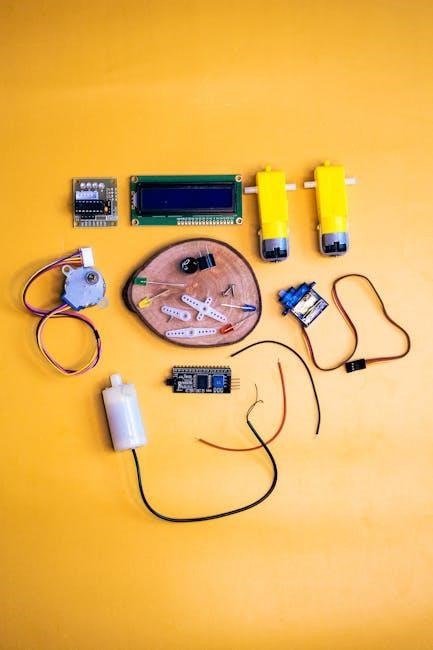
Essential Wiring Components
Proper wiring demands quality components for safety and reliability. Wiring harnesses and connectors ensure secure connections, resisting corrosion. Fuse holders and circuit breakers protect against overloads, preventing damage to the motor and battery. Marine-grade wiring is vital, designed to withstand the harsh boat environment. Don’t skimp on these essentials for a dependable system.
Wiring Harnesses and Connectors
Marine-grade wiring harnesses simplify installation and offer superior protection. Look for tinned copper wire to resist corrosion. Heat-shrink connectors provide a watertight seal, crucial in a boat environment. Properly crimped connections are essential; avoid loose connections. Quality connectors minimize resistance, maximizing power transfer to the trolling motor for efficient operation.
Fuse Holders and Circuit Breakers
Essential safety components, fuse holders and circuit breakers protect your trolling motor and boat’s electrical system. Install them as close to the battery as possible. Choose amperage ratings appropriate for the motor’s draw. Circuit breakers offer resettable protection, while fuses require replacement after a fault. Regular inspection ensures continued functionality.
Step-by-Step Wiring Instructions
Proper wiring is crucial for safe and efficient operation. Begin by disconnecting the battery. For 24-volt systems, connect batteries in series – positive to negative. Then, securely connect the wiring harness to the battery terminals, ensuring correct polarity. Double-check all connections before reconnecting the battery and testing the motor.
Connecting Batteries in Series (24-Volt Systems)
To achieve 24-volts, connect batteries in series. Begin by positioning the batteries closely. Connect a cable from the positive (+) terminal of the first battery to the negative (-) terminal of the second battery. The remaining negative terminal and positive terminal become your system’s output for connecting to the motor.
Wiring the Trolling Motor to the Battery
After connecting batteries (or using a single 12V), attach the trolling motor’s wiring. Connect the positive (+) wire from the battery setup to the positive wire of the motor. Similarly, connect the negative (-) wires. Ensure secure connections, utilizing appropriate connectors and, crucially, a fuse holder close to the battery’s positive terminal.
Decoding Trolling Motor Wiring Diagrams
Understanding wiring schemas is vital for correct installation and troubleshooting. Diagrams utilize symbols representing components like batteries, motors, fuses, and connectors. Familiarize yourself with these symbols – often found on page 9 of the user manual – to accurately interpret the wiring layout. Proper interpretation ensures safe and efficient motor operation.
Reading and Interpreting Wiring Schemas
Effectively reading schemas requires recognizing component representations and tracing connections. Begin by identifying the power source (battery) and motor. Follow the lines indicating wire paths, noting any inline components like fuse holders or circuit breakers. Schemas, often multilingual (English, French, Italian, German), provide a visual roadmap for successful wiring.
Common Wiring Diagram Symbols
Understanding symbols is key to decoding wiring diagrams. Relays, crucial in ULN2803A circuits, are represented distinctly. Battery symbols indicate polarity (+/-). Wire junctions signify connection points. Fuses are shown as breaks in the line with a specific symbol. Recognizing these allows for accurate tracing of electrical paths and troubleshooting potential issues.

Specific Motor Wiring Examples
Detailed wiring procedures vary by motor model. The Minn Kota TRAXXIS 55 requires specific connector arrangements. Diagrams illustrate proper battery connections for 12V and 24V systems. Understanding these examples, alongside the general ULN2803A circuit schema, is vital for successful installation and ensuring correct functionality of your trolling motor.
Minn Kota TRAXXIS 55 Wiring
The Minn Kota TRAXXIS 55 installation demands careful attention to connector placement and secure fastening. Resources detail key installation steps for a proper boat motor mount. Correct wiring ensures optimal performance and longevity. Refer to the provided diagrams and documentation for specific TRAXXIS 55 wiring configurations and safety guidelines;
General Trolling Motor Wiring Diagram (ULN2803A Circuit)
Utilizing the ULN2803A integrated circuit, this diagram illustrates propeller motor control via relays. The schematic details pin connections for efficient operation. Understanding this circuit is crucial for custom installations or troubleshooting. Proper implementation ensures reliable power distribution and motor functionality, maximizing trolling performance and battery life.
Troubleshooting Common Wiring Issues
Addressing wiring problems is vital for consistent trolling motor operation. Common issues include a complete lack of power, often due to loose connections or blown fuses, and intermittent running, signaling potential wiring faults. Careful inspection of connections, fuses, and the wiring harness is key to diagnosing and resolving these frustrating problems quickly and safely.
No Power to the Motor
If your trolling motor receives no power, begin with the simplest checks. Verify battery charge and secure connections at both the battery terminals and the motor itself. Inspect the fuse holder for blown fuses – replacement is crucial. Examine the wiring harness for any visible damage or loose connections, ensuring a complete circuit.
Motor Runs Intermittently
An intermittently running trolling motor often indicates a loose connection or wiring issue. Carefully inspect all wiring connections, from the battery to the motor, wiggling wires to check for temporary power loss. Check for corroded terminals and replace if necessary. A failing circuit breaker or a partially blown fuse can also cause this symptom.
Safety Precautions During Wiring
Always disconnect the batteries before commencing any wiring work to prevent accidental shorts and electrical shock. Ensure proper wire insulation and protection against abrasion and environmental factors. Use appropriately sized wiring for the current draw of the motor. Securely mount components and protect connections from water intrusion for safe operation.
Disconnecting Batteries Before Wiring
Prior to initiating any wiring procedures, completely disconnect both the positive and negative terminals from all batteries. This crucial step eliminates the risk of short circuits, accidental motor activation, and potential electrical shocks during the installation process. Verify disconnection with a voltage tester before proceeding.
Proper Wire Insulation and Protection
Employ marine-grade wiring with robust insulation to withstand the harsh boating environment. Securely route wires away from sharp edges, moving parts, and potential heat sources. Utilize conduit or protective sleeving where necessary, and ensure all connections are watertight to prevent corrosion and maintain reliable performance over time.

Tie Bar Kit and Wiring Considerations
The tie bar kit isn’t sold separately and is crucial for connecting the motor; wiring diagrams are located on page 9. Proper integration requires careful attention to detail. Refer to page 9 for battery connection instructions and pages 10 for motor adjustments and tiller control specifics, ensuring safe and effective operation.
Understanding Tie Bar Kit Integration

The tie bar kit, essential for motor connection, is not available as a standalone purchase. Its integration is vital for steering functionality. Consult the wiring diagram on page 9 for correct installation. Proper connection ensures synchronized motor movement, enhancing control and maneuverability during operation on the water.
Wiring Diagram Location (p.9 Reference)
Crucially, the detailed wiring diagram is located on page 9 of the user manual. This schema, available in multiple languages (English, French, Italian, German, Spanish), illustrates the electrical connections for proper installation. Refer to it when connecting batteries and the motor, ensuring correct polarity and secure connections for safe operation.
Adjusting and Controlling the Motor
Once wired correctly, understanding motor adjustments is key. Page 10 of the manual details how to utilize adjusting features for precise control. This includes mastering speed and directional control via the tiller, allowing for nuanced maneuvering. Proper adjustment maximizes efficiency and responsiveness during operation, enhancing the overall boating experience.
Using Adjusting Features (p.10 Reference)
Referencing page 10, the user manual outlines crucial adjustment procedures. These features allow for fine-tuning of the trolling motor’s performance, optimizing it for various fishing conditions and boat types. Mastering these adjustments ensures precise boat positioning and control, contributing to a more successful and enjoyable angling experience on the water.
Controlling Speed and Direction with the Tiller (p.10 Reference)
Page 10 of the manual details tiller operation for precise control. The tiller manages both speed and steering, enabling nuanced adjustments for accurate positioning. Understanding its functionality is key to effective trolling, allowing anglers to maintain a consistent speed and direction while presenting lures or baits effectively in various conditions.

Maintenance and Long-Term Care
Regular maintenance extends your trolling motor’s lifespan and ensures reliable performance. For prolonged trolling sessions, the manual recommends more frequent motor oil changes – a crucial step often overlooked. Consistent care, including inspecting wiring for corrosion and ensuring secure connections, prevents issues and maximizes the motor’s longevity on the water.
Replacing Motor Oil for Extended Trolling
When engaging in extended trolling, frequent motor oil replacement is vital for optimal performance. The user manual emphasizes this preventative measure, as prolonged use increases wear and tear. Regularly changing the oil ensures smooth operation, reduces friction, and prevents internal damage, ultimately extending the trolling motor’s service life.
Drum Motor Installation Wiring
The Drum Motor Installation Manual provides crucial details for successful electrical connections. It outlines a step-by-step process, ensuring proper wiring for installation and ongoing maintenance. Following these instructions carefully guarantees safe and efficient operation of the drum motor, maximizing its performance and longevity on your vessel.
Electrical Connection Instructions
Detailed electrical connection instructions are paramount for drum motor installation. The manual emphasizes a secure wiring setup, referencing wiring diagrams and schematics (available in multiple languages). Proper connection ensures optimal power delivery and prevents potential electrical hazards, contributing to the motor’s reliable and long-lasting performance on the water.
User Manual Overview
This user manual serves as a complete guide for your 12-24V trolling motor wiring diagram. It’s designed to familiarize you with all features, the installation process, and crucial wiring details. The manual provides a pathway to maximizing your product’s potential, ensuring a smooth and successful boating experience with clear instructions.
Navigating the 12-24V Trolling Motor Wiring Diagram Guide
Effectively utilizing the 12-24V wiring diagram is key to a successful installation. This guide details essential components, connection points, and troubleshooting steps. Refer to page 9 for battery connections and wiring diagrams, and page 10 for motor adjustments and tiller control information, ensuring a safe and efficient setup.
Additional Resources and Support
For further assistance beyond this guide, consult the full 87-page document (3MB) detailing drum motor installation, electrical connections, and maintenance. User manuals, like the one for the 24-Volt system, provide comprehensive overviews. Explore Minn Kota TRAXXIS 55 resources for specific motor installation steps and secure mounting procedures.